EN
11_11. 6755532_02
The ANK heat pumps are completely wired at the
-
cal mains, downstream from a unit switch, accord-
ing to that envisioned by the Standards in force on
this subject in the country of installation.
It s also advised to check that:
the electrical mains features are suitable
electrical data table, TAB. also taking into
-
The unit is only powered when installa-
phase, and earth wires.
The power supply line must have a
against short circuits and dispersions to
earth, which isolates the system with
The voltage must be within a tolerance
of ±10% of the nominal power supply
voltage of the machine (for unbalanced
three-phase unit max 3% between the
not respected, contact the electric energy
-
cording to the Standards in force on this
The use of an omnipolar magnet circuit
breaker switch is mandatory, in compli-
ance with the IEC-EN Standards (contact
the basis of the electric data table shown
below, installed as near as possible to the
appliance.
considered responsible for any damage
-
For units with three-phase power sup-
phases.
-
mended for maximum lengths of 50m.
up to the PLANNER to calculate the appropriate
line switch, the power supply line as well as the
depending on:
the length
the type of cable
-
-
ture.
:
1. -
is open.
2. Open the front panel
3. -
work for the main electric power supply
cable and for the cables of the other external
installer.
4. It is forbidden to access with
manual.
5. Avoid direct contact with not
insulated copper piping and with
compressor.
6.
to the electric layout supplied
with the unit.
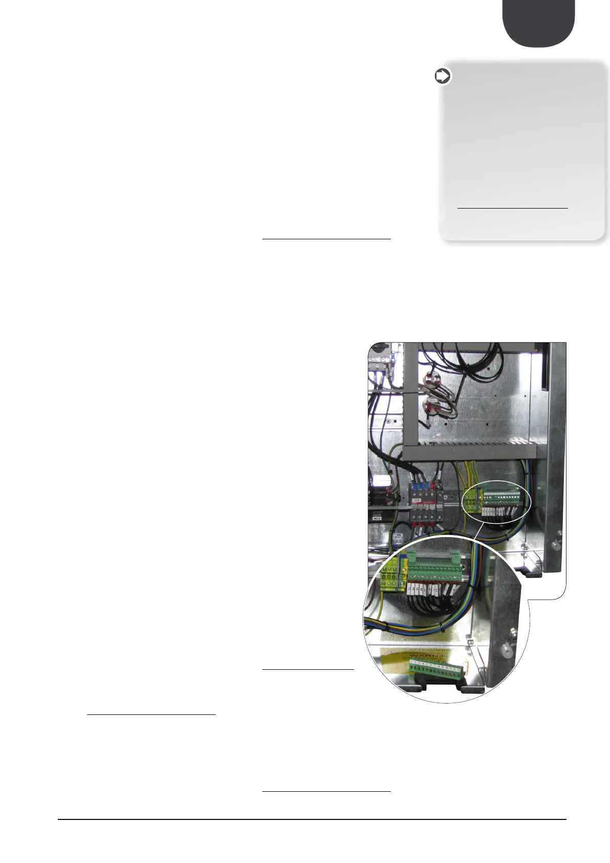
7.
of the unit bring a power supply
cable to the electric control
board inside the unit and con-
nect to the U-N and PE clamps
8.
9.
removed for the electric connec-
electrically powering the unit.
10.
“ON”.
All clamps to which reference is
are part of the 13 POLE removable
terminal board situated inside the
electric control board and con
-
24.3.1. SUMMER/WINTER REMOTE CONTROL
To prepare a summer/winter remote switch-
must be
performed with standard set-
tings. Only when the inspection
has been completed can the
functioning Set Point values by
changed.
Before start-up, power the unit
for at least 12-24 hours position-
ing the protection magnet circuit
breaker switch and the door lock
isolating switch at ON.
Make sure that the control panel
is off in order to allow the com-
pressor sup oil to heat.