Do you have a question about the AERMEC ANL 100-HP and is the answer not in the manual?
Details components like compressors, heat exchangers, and valves in the refrigerant system.
Explains components of the water circuit, including filters, pumps, and vessels.
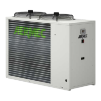
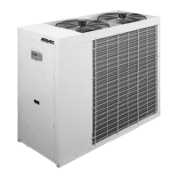
Describes the unit's physical structure, casing, and axial fans.
Covers pressure switches, transducers, and safety devices for unit operation.
Details the electrical panel, controller, and associated components.
Information on power status, compressor, operating mode, and alarms displayed.
Details on displayed water, refrigerant, air temperatures and pressures.
Diagram and components for the standard ANLH hydraulic circuit.
Diagram and components for the ANL HP hydraulic circuit.
Diagram and components for the ANL HA hydraulic circuit.
Lists factory-installed accessories like antivibration supports.
Table detailing accessory compatibility by model and version.
Impact of salt and electrolytes on heat exchangers in coastal areas.
Effects of atmospheric emissions and industrial pollutants on exchangers.
Combined risks of salt and industrial emissions accelerating corrosion.
Pollution from motor vehicles and heating systems impacting exchangers.
Pollution from ammonia, diesel exhaust, and local weather affecting exchangers.
Factors like wind, dust, and road salts influencing heat exchanger selection.
Tables detailing cooling/heating capacity, input power, EER, and COP.
Diagram and table showing unit dimensions and weight distribution.
Graph illustrating operational limits for cooling mode by temperature.
Graph illustrating operational limits for heating mode by temperature.
Graph showing pressure drops in cooling mode based on water flow.
Graph detailing pressure drop across the water filter.
Graph showing useful head for ANL 100 and ANL 150 models.
Guidance on minimum water volume for stable unit operation.
Information on expansion vessel capacity and maximum water content.
Factors for adjusting performance based on deviations in water temperature.
Corrective factors for capacity and input power due to fouling.
Correction factors for Ethylene and Propylene Glycol mixtures.
Overview of risks and essential safety information in the manual.
Required PPE for safe handling, installation, and maintenance operations.
Rules for qualified personnel and safe product usage and installation.
Warnings on water filters, seal tests, pipe handling, and fluid types.
Warnings about plant connections, earthing, and electrical maintenance safety.
Warnings regarding refrigerant gas, brazing, flames, and leak recovery.
Safety measures for mobile parts, hot/cold surfaces, and panels.
Safety symbols indicating hot surfaces, electricity, moving parts, and sharp elements.
Procedures for inspecting the unit upon delivery and checking contents.
How to identify the unit using packaging labels and rating plates.
Safety procedures for handling packaging and removing the unit.
Instructions for safely moving the unit using a forklift.
Instructions for safely lifting the unit using hoists or cranes.
Recommendations for storing units prior to installation.
Criteria for selecting an appropriate outdoor installation location.
Guidelines for unit placement and installing anti-vibration supports.
Required clearance for single unit installation and maintenance access.
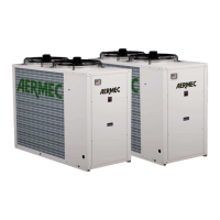
Considerations for installing multiple units in proximity.
Instructions on connecting the unit to the hydronic system.
Recommended water quality parameters for heat exchangers.
Solutions to prevent heat exchanger freezing during winter shutdown.
Guidelines for using glycol/water solutions for freeze protection.
Diagram showing the overall physical dimensions of the unit.
Diagram indicating the location of water inlet and outlet connections.
Notes on cable glands, short-circuit power, mains features, and phase connections.
Tables detailing electrical data for 220V and 460V power supplies.
Diagram and explanation for connecting the auxiliary control board.
Steps for connecting the unit to the main electrical power supply safely.
General notice about responsibility for errors during commissioning.
Pre-power checks for safety, connections, and refrigerant leaks.
Checks and precautions required when the unit is operating.
Checks for hydraulic connections, pump operation, and flow switch.
Final checks and procedures before starting the unit.
Warnings and safety measures for maintenance personnel.
Risks related to refrigerant gas, moving parts, sharp edges, and pressure.
Precautions for chemical, fire, and environmental hazards during maintenance.
Risks from pressure and temperature extremes during maintenance.
Procedures for safe disposal of the unit and its components.
Steps for performing routine and extraordinary maintenance tasks.
Procedures for inspecting and controlling the machine when powered off.
Procedures for cleaning the machine when powered off.
Table of general maintenance tasks and recommended frequencies.
Table of hydraulic and compressor circuit maintenance tasks.