9
4 INPUT/OUTPUT MENU
The input/output menu shows many of the values measured by the various probes
and transducers on the unit. You cannot set any values via this menu, but it gives
important operating information such as the defrosting status and so on.
NOTE: The top-left corner of each window shows which compressor is currently
providing the displayed data (U:1,2,3 o 4); to switch between compressors (only
possible from Master unit), refer to that explained in paragraph "3.3Unit operating
status information (real time data)p.7".
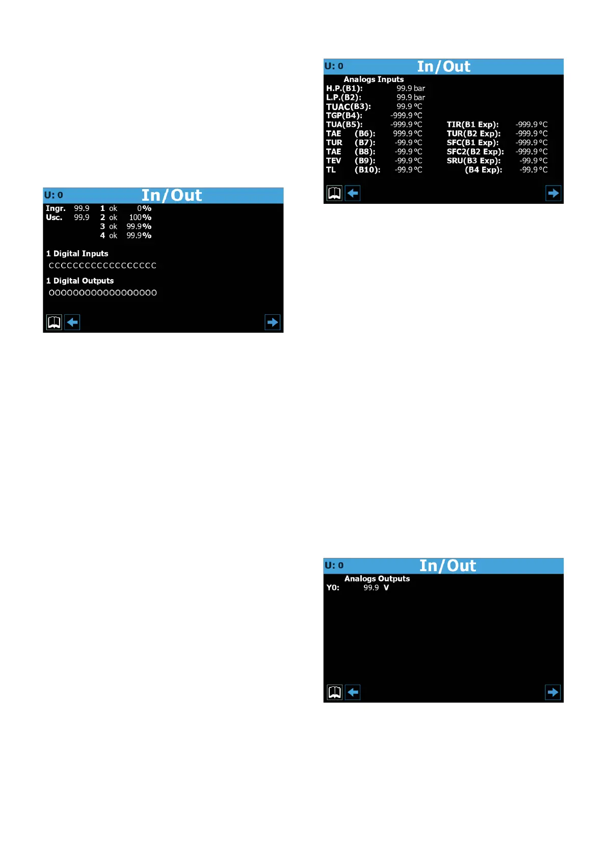
4.1 GENERAL STATUS OF INPUTS/OUTPUTS AND
COMPRESSORS
— Indicates to which compressor the displayed data refers (U:1 = Master; U:2 =
Slave 1; U:3 = Slave 2; U:4 = Slave 3)
— Actual water temperature value detected at unit inlet
— Actual water temperature value detected at unit outlet
— Status of compressor 1 and actual percentage load of use of the same; the com-
pressor status can be:
ok = indicates that the compressor è operating;
al = indicates that the compressor is stopped for alarm;
sp = indicates that the compressor is currently in “safety partialisation” mode;
F = indicates that the Freecooling mode is currently active;
WW = indicates that the compressor is currently in stand-by for safety dierential;
PD = indicates that the compressor is currently in stand-by for pump-down;
--- = compressor not present;
— Status of compressor 2 and actual percentage load of use of the same; the com-
pressor status can be:
ok = indicates that the compressor è operating;
al = indicates that the compressor is stopped for alarm;
sp = indicates that the compressor is currently in “safety partialisation” mode;
F = indicates that the Freecooling mode is currently active;
WW = indicates that the compressor is currently in stand-by for safety dierential;
PD = indicates that the compressor is currently in stand-by for pump-down;
--- = compressor not present;
— Status of compressor 1 and actual percentage load of use of the same; the com-
pressor status can be:
ok = indicates that the compressor è operating;
al = indicates that the compressor is stopped for alarm;
sp = indicates that the compressor is currently in “safety partialisation” mode;
F = indicates that the Freecooling mode is currently active;
WW = indicates that the compressor is currently in stand-by for safety dierential;
PD = indicates that the compressor is currently in stand-by for pump-down;
--- = compressor not present;
— Each character of this string (starting from left) indicates the status of a digital
input; the rst character indicates the status of ID1, the second of ID2, and so on
up to ID18 (O = open; C = closed)
— Each character of this string (starting from right) indicates the status of a digital
output; the rst character indicates the status of C1, the second of C2, and so on
up to C18 (O = open; C = closed)
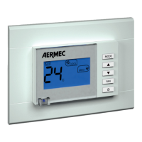
4.2 STATUS OF ANALOGUE INPUTS
— Indicates to which compressor the displayed data refers (U:1 = Master; U:2 =
Slave 1; U:3 = Slave 2; U:4 = Slave 3)
— Current pressure value measured on the high-pressure side of the refrigerant
circuit
— Current pressure value measured on the low-pressure side of the refrigerant
circuit
— This parameter may vary depending on the unit displayed:
TIA (B3) = Indicates the actual temperature value read at evaporator input (master
only);
TUAC (B3) = Indicates the actual temperature value read at common water outlet,
in case of outlet adjustment with multiple evaporators in parallel (only for Slave 1
unit);
— Indicates the actual temperature value read on the high pressure side of the
cooling circuit
— Indicates the current temperature value measured on the evaporator outlet
— Indicates the actual current value read at amperometric transformer input
— This parameter may vary depending on the unit displayed:
(B7) = Indica lo stato attuale dell'ingresso multifunzione (solo unità Master);
TUR (B7) = Indicates the actual temperature value read at recovery unit output (for
Slave units only);
— Indicates the current outside air temperature
— Indicates the actual temperature value read on the gas side at evaporator input
— Indicates the actual liquid temperature value
— Indicates the actual temperature value of the total recovery inlet water
— Indicates the actual temperature value of the total recovery outlet water
— Indicates the actual temperature value of the freecooling inlet water
— Indicates the actual temperature value of the freecooling outlet water
— Indicates the actual temperature value of the intermediate heat exchanger inlet
water
— B4 Exp: Not used
4.3 STATUS OF ANALOGUE OUTPUTS
— Indicates to which unit the displayed data refers (U:1 = Master; U:2 = Slave 1; U:3
= Slave 2; U:4 = Slave 3)
— Indicates the current voltage for the fan control