6. DESCRIPTION
OF COMPONENTS
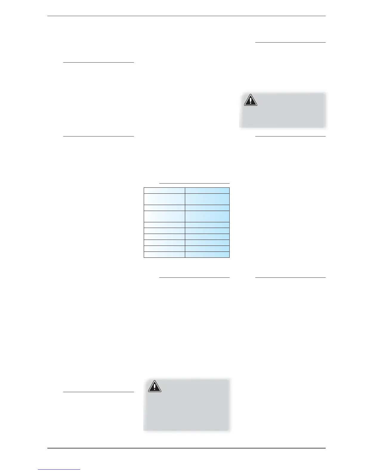
6.1. STRUCTURE
Base and support structure
Made up from hot galvanised sheet steel
elements with suitable thickness. All parts
painted with polyester powder paints (RAL
9002), resistant to atmospheric agents.
Realised in a way to allow total accessibility
to the components
internal components. All panels are
covered with sound-absorbent material
with suitable thickness.
6.2. COOLING CIRCUIT
Compressor
High efficiency scroll hermetic compressors
(mounted on anti-vibration supports),
activated by a 2-pole electric motor with
internal heat protection.
Evaporator
Plate type (AISI 316). It is insulated externally
with closed cell material to reduce thermal
dispersions.
Condenser
Plate type (AISI 316). It is insulated externally
with closed cell material to reduce thermal
dispersions.
Dehydrator filter,
Hermetic-mechanical with cartridges made
of ceramic and hygroscopic material, able
to withhold impurities and any traces of
humidity present in the cooling circuit.
Biflow type up to model 080.
Indicator for liquid passage with
humidity presence signal,
Used to check the refrigerant gas load and
the eventual presence of humidity in the
cooling circuit.
Electronic thermostatic valve
(STANDARD FOR ALL MODELS).
The valve modulates the flow of gas to the
evaporator, according to the heat load, in
order to ensure a correct heating level of
the intake gas.
One-way valves
(FOR MODELS 100-140-160).
Allows the passage of the refrigerant
in just one direction.
4-way cycle reverse valve
Inverts the flow of refrigerant gas.
6.3. MAIN OPERATIONS
The WRL-H heat pumps are supplied as per
standard with:
• Water filter; Equipped with steel
filtering mesh; prevents the heat
exchangers from clogging.
• Differential pressure switch; It checks
that here is water circulation inside the
heat exchangers. Adversary, it blocks
the unit
• Safety valve (6 bar).
Equipped with a piped discharger
and intervenes by discharges the
over pressure in case of anomalous
pressures.
• Expansion tank (for version with
storage tank/storage tank+pumps)
With nitrogen pre-load membrane.
• Air vent
• Drain cock
• Cut-off cock
Below find the description of the hydraulic
components, present in the various other
versions. WRLH°TBPQ.
6.4. WATER FEATURES
6.5. COMPONENTS THAT CAN BE
CONFIGURED
The components that can be selected by
the configurator are:
• 3-speed ON/OFF pump (up to 080
model) or standard three-phase one-
speed pump for 100-140-160 models.
• Larger single speed three phase pump
(100-140-160 models).
• Pump with phase cut set-up (up to 080
model).
• Inverter pump (up to 080 model).
• Storage tank; “100 litres WRL 025-080”,
“150 litres WRL 100-160”.
The following is available for well/sheet
water applications:
• 2-way modulating valve (0÷10 V
signal). Maximum differential pressure
4bar/40kPa.
ATTENTION:
In case of power failure
the valve remains locked
in the working position. In
order to avoid unnecessary
water consumption, it is
recommended to install,
upstream of the water mains
supply, a shut-off device
6.6. DHW SIDE HYDRAULIC
COMPONENTS
• Water filter; Equipped with steel
filtering mesh; prevents the heat
exchangers from clogging.
• TOTAL RECOVERY (OPTIONAL)
Plates type (AISI 316), it is insulated
externally with closed cell material to
reduce heat loss.
In the event of installation
(pump/external total
recovery) for correct
functioning of the machine it is
mandatory that it is managed
by the regulation of the same.
6.7. SAFETY AND CONTROL
Low pressure transducers
Placed on the low pressure side of the
cooling circuit, it signals the work pressure
to the control board, generating a pre-
warning in case of anomalous pressures.
High pressure transducer
Placed on high pressure side of cooling
circuit, signals the work pressure to control
board, generating a pre-warning in case
abnormal pressure occurs.
High pressure pressure switch
With fixed calibration, placed on high
pressure side of cooling circuit, inhibits
functioning of compressor if abnormal work
pressure occurs.
Watertemperature probe (DHW);
The unit is delivered supplied with n° 1
temperature probe for any DHW tank.
6.8. ELECTRIC CONTROL BOARD
AND REGULATION
Electric power and control board,
manufactured in compliance with the EN
60204-1/IEC 204-1 Standards, complete
with:
• door lock main isolating switch,
• magnet circuit breaker switches and
contactors for compressors,
• phase sequence control,
• clamps for signalling the remote alarm,
• clamps for signalling compressor
switch-on status,
• clamps for differential pressure switch
alarm signal,
• clamps for external air temperature
probe (ACCESSORY),
• soft-start (OPTIONAL),
• control circuit numbered cables,
• clamps for 3-way valve,
• 0-10V clamps for modulating valve
control.
"Chiller" water set-point compensation due
to external temp.
Adaptation of the unit set point depending
on the external temperature, allowing
greater comfort and energy saving. The
PH 6-8
Electric
conductivity
less than 200 mV/
cm (25°C)
Chloride ions less than 50 ppm
Sulphuric acid
ions
less than 50 ppm
Total iron less than 0.3 ppm
Alkalinity M less than 50 ppm
Total hardness less than 50 ppm
Sulphur ions none
ammonia ions none
Silicone ions less than 30 ppm
9
IWRLTY. 1201. 5890974_06