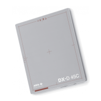
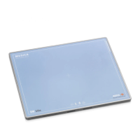
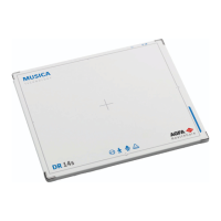
DX-D 45C, DX-D 45G
1.
DR Detector battery
Supplies power to the detector during wireless communication.
2.
DR Detector battery lock lever
Unlock the battery.
3.
Battery status indicator
4.
Antenna of the wireless network adapter
Operation in wireless configuration.
5.
On/off switch
6.
Status indicators
• Blue indicator shows data communication status.
• Orange indicator shows if the detector is ready.
• Green indicator shows power on/off status of the detector.
7.
S-button
No function is attributed.
8.
DR Detector connector
Operation in wired configuration.
9.
Effective imaging area border and center position indication
Figure 4: DR Detector operation controls
Related Links
Detector Status Indicators on page 90
DX-D 45C, DX-D 45G on page 106
20 | DX-D 45C, DX-D 45G | Introduction to the DR Detector
0292B EN 20190401 1627