117
Chapter 5 Theory of Operation
Phase Locked Loops
4
5
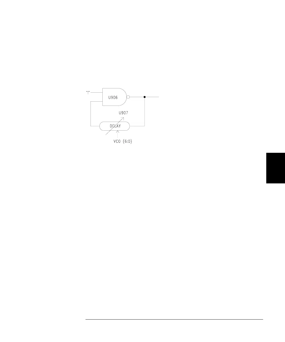
The triggered PLL synthesizer, U904, drives U905 which shifts and
scales the output voltage to match the input requirements of varactor
CR901. U907 is a programmable delay, fed back upon itself through a
differential RC network (the capacitance of CR901, resistors R929 and
R930, and gate U906). U907 is programmed through the VCO(6:0) lines
from the Synthesizer IC.
VCO(6:0) are chosen to set the frequency as close as possible to the
desired frequency, then the loop adjusts the voltage on the varactor to
fine tune the frequency.
When the instrument is generating pulses, PRI_nTRGe is low to enable
U907; otherwise, PRI_nTGRe is high. TRIG_SYNC* for the Trigger
Delay Circuit goes low briefly when the instrument is triggered,
disabling U906 and stopping the oscillator. When TRIG_SYNC* goes
high again, the oscillator starts up synchronized to the trigger.

 Loading...


