65
Chapter 4 Calibration Procedures
+10 dB Range Flatness Verification
4
4
+10 dB Range Flatness Verification
This procedure checks the high frequency ac amplitude flatness above
100 kHz on the +10 dB attenuator range.
1 Connect the power meter to measure the output amplitude of the
instrument as shown on page 63.
2 Set the power meter reference level to equal to the calculated
100kHz_10dB_offset value. This sets the power meter to directly read
the flatness error specification. 100kHz_10dB_offset is calculated on
the Amplitude and Flatness Verification Worksheet.
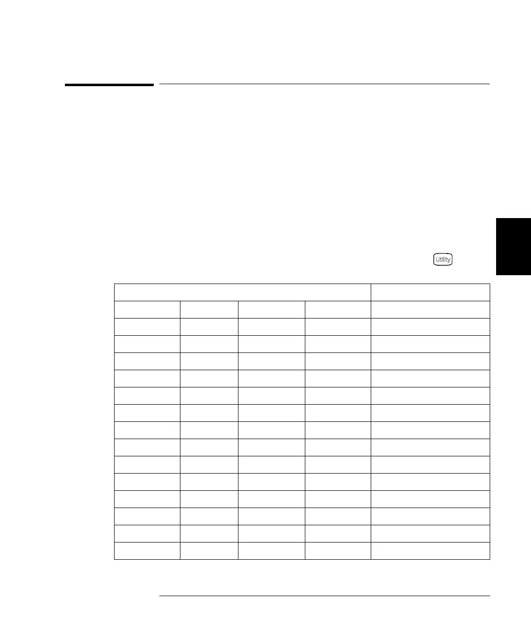
3 Set the instrument to each output described in the table below and
measure the output amplitude with the power meter. Press to set
the output impedance to 50Ω. Be sure the output is enabled.
4 Compare the measured output to the test limits shown in the table.
Agilent 33250A Measurement
Output Setup Function Amplitude Frequency Nominal Error
Q 50 Ω Sine Wave +13.00 dBm 100.000 kHz 0 dB ± 0.086 dB
50 Ω Sine Wave +13.00 dBm 200.000 kHz 0 dB ± 0.086 dB
50 Ω Sine Wave +13.00 dBm 500.000 kHz 0 dB ± 0.086 dB
50 Ω Sine Wave +13.00 dBm 1.500 MHz 0 dB ± 0.086 dB
50 Ω Sine Wave +13.00 dBm 5.000 MHz 0 dB ± 0.086 dB
Q 50 Ω Sine Wave +13.00 dBm 10.000 MHz 0 dB ± 0.086 dB
50 Ω Sine Wave +13.00 dBm 25.000 MHz 0 dB ± 0.177 dB
50 Ω Sine Wave +13.00 dBm 40.000 MHz 0 dB ± 0.177 dB
Q 50 Ω Sine Wave +13.00 dBm 50.000 MHz 0 dB ± 0.177 dB
50 Ω Sine Wave +13.00 dBm 60.000 MHz 0 dB ± 0.423 dB
50 Ω Sine Wave +13.00 dBm 65.000 MHz 0 dB ± 0.423 dB
50 Ω Sine Wave +13.00 dBm 70.000 MHz 0 dB ± 0.423 dB
50 Ω Sine Wave +13.00 dBm 75.000 MHz 0 dB ± 0.423 dB
Q 50 Ω Sine Wave +13.00 dBm 80.000 MHz 0 dB ± 0.423 dB

 Loading...


