104
Chapter 5 Theory of Operation
Digital Waveform Translator
5
Digital Waveform Translator
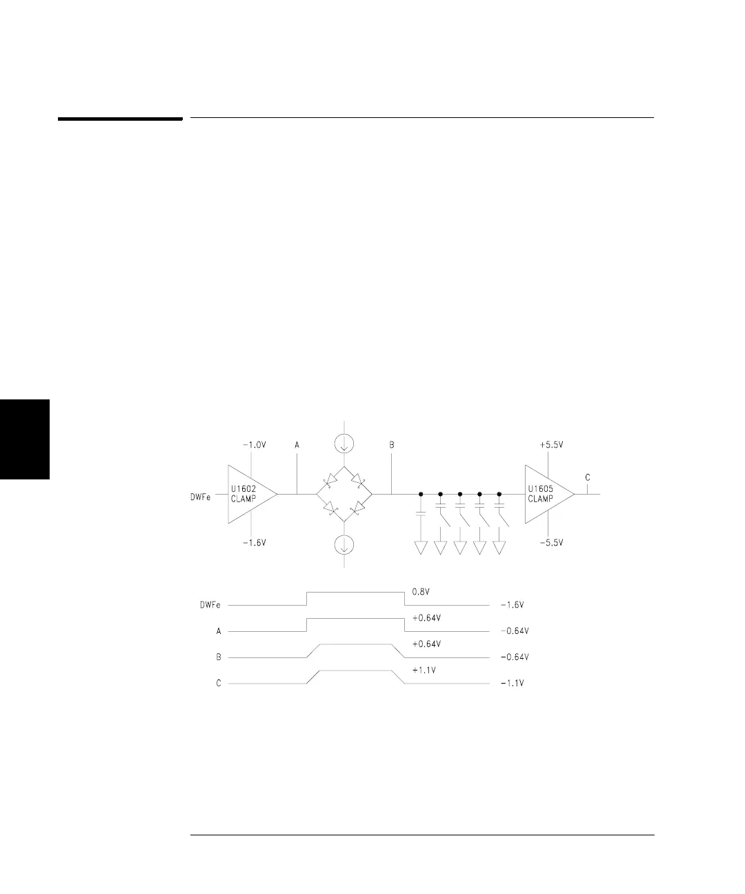
See “A1 Variable-Edge Level Translation Schematic” on page 200.
Digital Waveform Translator converts the square or pulse waveform’s
(DWFe) ECL levels to the ±1 V levels required by Amplitude Multiplier.
It also sets the rise and fall time of the square wave or pulse.
The input signal, DWFe, is amplified and level translated to ±640 mV
by clamping amplifier U1602. Clamping levels are set by R1613, R1616,
R1628, and R1631. U1602’s output drives a diode switch (CR1601 and
CR1602) that steers currents from Q1606 and Q1608 into one of five
integrating capacitors (C1609 through C1613). The charge current is set
by U1601, Q1601, Q1602, and associated components, according to the
value of V_LEDGE (0 to +2.5 V). Similarly, the discharge current is set
by U1603, Q1607, Q1608, and associated components, according to the
value of V_TEDGE (0 to –2.5 V).
The voltage on the integrating capacitor is amplified and buffered by
another clamp amplifier, U1605, to ±1.1 V as required by the Amplitude
Multiplier. U1605’s clamp levels are set by U1604 and associated
components.

 Loading...


