135
Chapter 6 Service
Troubleshooting Hints
4
6
Power Supplies
Verify the power supplies generated on the A1 board.
WARNING Shock Hazard. To check the power supplies, remove the instrument
cover as described in “Disassembly”, on page 140. Be sure to use the
correct ground point when checking the supplies.
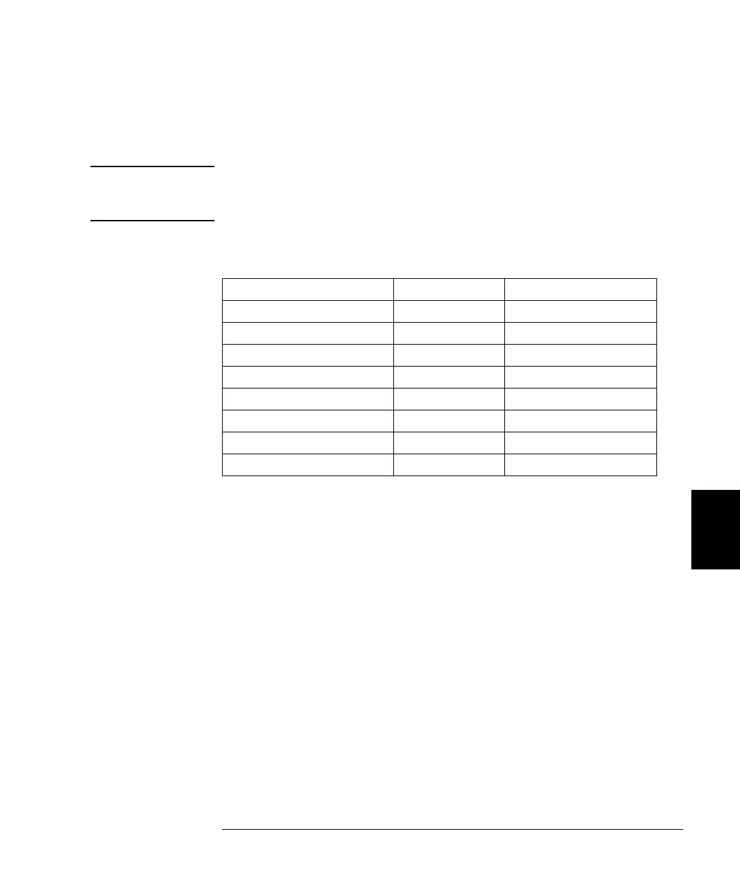
The power supply voltages are tabulated below.
• Power supply test points are marked on the A1 circuit board.
• Circuit failures can cause heavy supply loads which may pull down
the regulator output voltage.
• Always check that the power supplies are free of ac oscillations
using an oscilloscope.
• The main power supply contains a fuse rated F5AH250V.
Replacing this fuse is not recommended. Replace the entire main
power supply assembly.
Power Supply Minimum Maximum
+12v_ER 11.4 V 12.6 V
+5V_ER 4.75 V 5.25 V
–5.2 V –5.46 V –4.94 V
–16 V –16.8 V –15.2 V
+16 V 15.2 V 16.8 V
+5.2 V 4.94 V 5.46 V
+3.3 V 3.135 3.465
–2.1 V –2.205 –1.995

 Loading...


