5
Technical Information
Start-Up
68/104 Agilent 4UHV Ion Pump Controller User Manual / 87-900-137-01 (A)
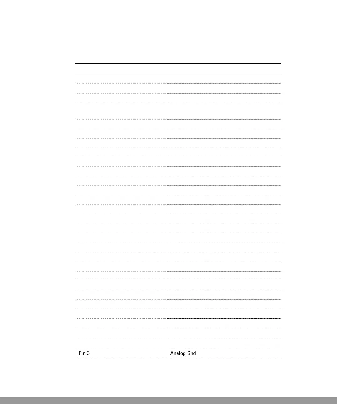
Table 4
Component Description
Remote I/O Signal Listing
Pin 4 +24V +/- 10%, max. current 60mA
Pin 5 Reserved
Fault A unique fault relay for all channels and for all
errors.
Pin 12 NC Fault Relay
Pin 13 NO Fault Relay
Pin 31 Common Fault Relay
Channel 1
Input
Pin 6 CH1 on/off
Pin 7 CH1 protect
Pin 8 CH1 step
Pin 22 Digital Gnd
Analog Output
Pin 1 Analog 1
Pin 3 Analog Gnd
Digital Output
Pin 17 CH1 NC Set-point Relay
Pin 18 CH1 (Common) Relay
Pin 19 CH1 NO Set-point Relay
Channel 2
Input
Pin 9 CH2 on/off
Pin 10 CH2 protect
Pin 11 CH2 step
Pin 22 Digital Gnd
Analog Output
Pin 2 Analog 2
Pin 3 Analog Gnd
This Manual: http://www.manuallib.com/file/2630540
 Loading...