Chapter 5 Service
Troubleshooting Hints
102
Bias Supplies Problems
Check that the input to the voltage regulators of the bias supplies is at least 1 V greater
than their output.
Circuit failures can cause heavy loads of the bias supplies which may pull down the
regulator output voltages.
Check the voltages of bias supplies as tabulated below.
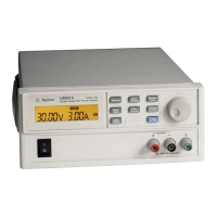
Table 5-1. Bias Supplies Voltages
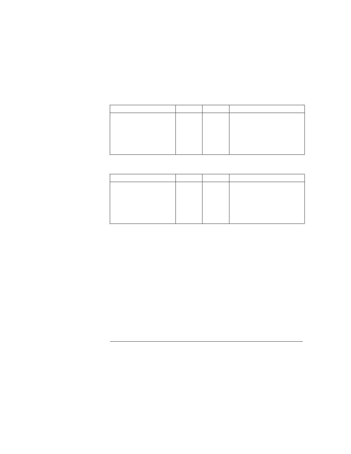
Table 5-2. Bias Supplies Voltages (MY53xx6xxx)
Some circuits produce their own local bias supplies from the main bias supplies. Be
sure to check that these local bias supplies are active. In particular, the ADC (analog-
to-digital converter), ac input, and front panel sections have local bias supplies.
Always check that the power supplies are free of ac oscillations using an oscilloscope.
Failure of bias supplies will cause many self-test failures.
Bias Supply Minimum Maximum Check At
+5V Floating
-5.1V Floating
+15V Floating (±25V supplies)
-15V Floating (±25V supplies)
+15V Floating (+6V supplies)
-15V Floating (+6V supplies)
+5V Ground Ref.
4.75 V
-4.75 V
14.25 V
-14.25 V
14.25 V
-14.25 V
4.75 V
5.25 V
-5.25 V
15.75 V
-15.75 V
15.75 V
-15.75
5.25 V
U1 pin 2 (on the top Board)
Anode of VR4 (on the top Board)
Cathode of CR16 (on the top Board)
Anode of CR18 (on the top Board)
U25 pin 2 (on the bottom Board)
U24 pin 3 (on the bottom Board)
U11 pin 3 (on the bottom Board)
Bias Supply Minimum Maximum Check At
+5V Floating
-5.1V Floating
+15V Floating (±25V supplies)
-15V Floating (±25V supplies)
+15V Floating (+6V supplies)
-15V Floating (+6V supplies)
+5V Ground Ref.
4.75 V
-4.75 V
14.25 V
-14.25 V
14.25 V
-14.25 V
4.75 V
5.25 V
-5.25 V
15.75 V
-15.75 V
15.75 V
-15.75
5.25 V
U40 pin 6 (on the top Board)
Anode of VR1 (on the top Board)
Cathode of CR4 (on the top Board)
Anode of CR7 (on the top Board)
U1 pin 2 (on the bottom Board)
U2 pin 3 (on the bottom Board)
U3 pin 3 (on the bottom Board)

 Loading...