Chapter 3 Calibration Procedures
General Calibration/Adjustment Procedure
74
13 Read the DVM and change the second current value on the display to match the
computed current (DVM reading
÷ by shunt resistance).
For example, if the computed value is 4.999 A, adjust the current to 4.999 A using
the knob and arrow keys.
Notice that you should wait for the DVM reading to stabilize for accurate calibration.
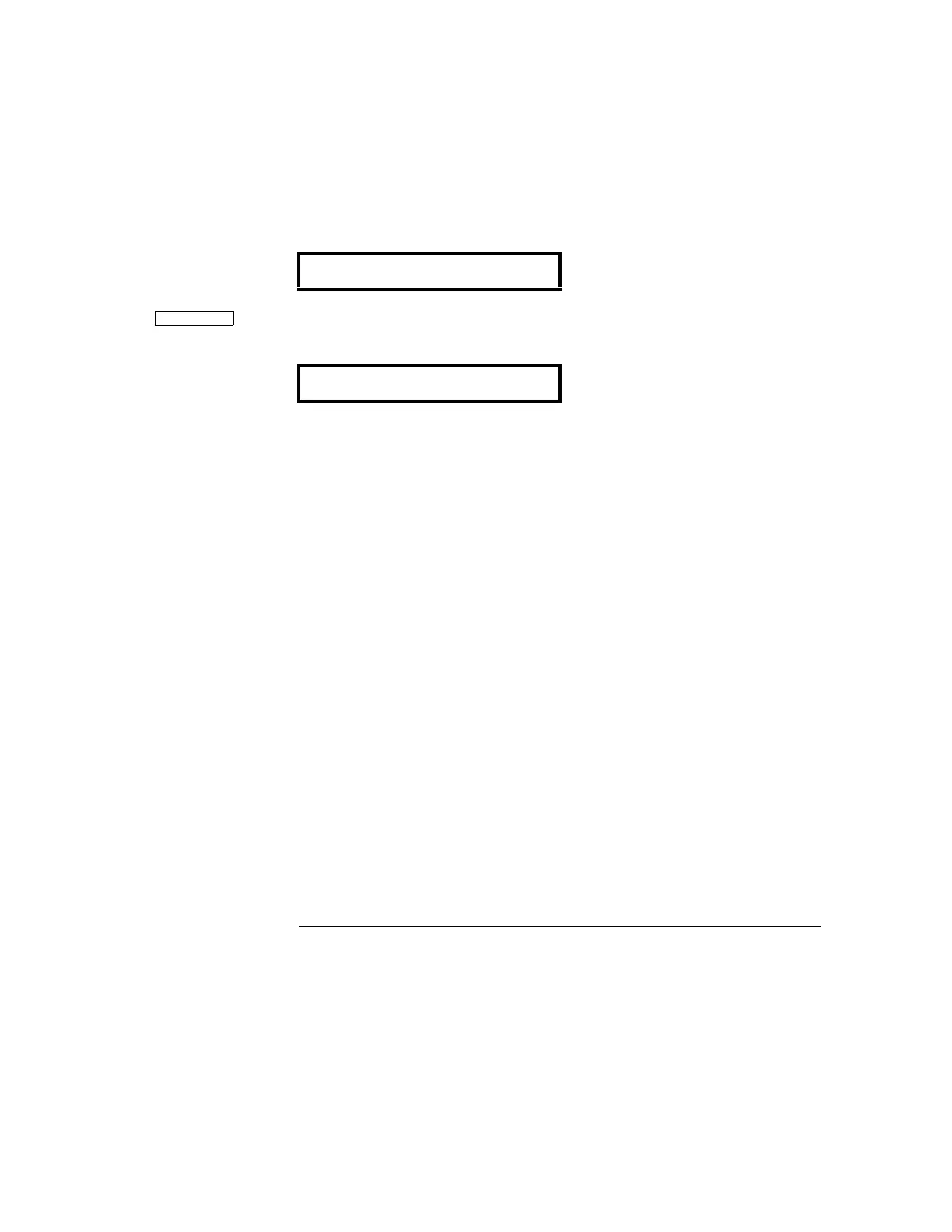
14 Pressing the "Calibrate" key saves the new calibration constants for the +6V
output current and goes to the voltage calibration mode for the +25V supply.
If the entered number is within an acceptable range, a "CALIBRATING" message
appears for one second to indicate that the calibration is successful and that new
calibration constants of "SETUP 2" are stored. Then, the display shows the above
message to indicate that the power supply is ready for the voltage calibration for +25V
supply.
If the entered number is not correct, an "INVALID DATA" message appears for one
second and the display shows the second voltage calibration point again. If the
calibration fails, a "CAL FAIL" message appears for one second and the display shows
the "CAL SETUP 2" for the current calibration of the +6V supply again.
15 Repeat steps (5) through (14) for the voltage and current calibration of the +25V
supply (replace +6V with +25V in all the text).
You can calibrate the output voltage and current of the +25V supply easily in the same
manner. Notice that you should connect a shunt across (+) and (COM) terminals of
the ±25V supply for the +25V supply current calibration.
16 Repeat steps (5) through (14) for the voltage and current calibration of the -25V
supply (replace +6V with -25V in all the text).
You can also calibrate the output voltage and current of the -25V supply easily in the
same manner. Notice that you should connect a shunt across (-) and (COM) terminals
of the ±25V supply for the -25V supply current calibration.
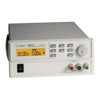
I HI +4.999 A
CAL SETUP 3

 Loading...