Chapter 1 1-7
GSM Use Model
Identifying Interfering Signals
CAUTION Use a simple attenuator test to determine whether displayed distortion
components are true input signals or internally generated signals
caused by mixer overload. Press
AMPLITUDE, Attenuation, and ⇑ to
increase the attenuation. If the amplitude of the suspected signal
changes, then it is internally generated. Continue increasing the
attenuation until the displayed distortion does not change, then
complete the measurement.
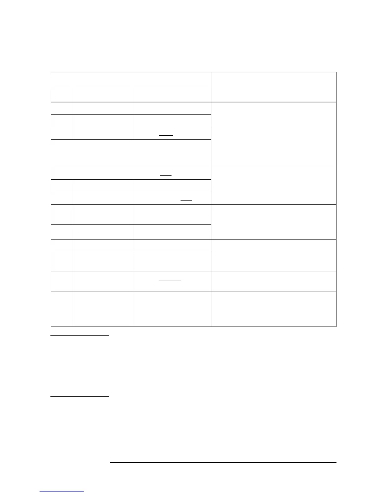
Table 1-2 Key Press Procedure for Identifying Interference Signals
Key Press Procedure Remarks
Step Front-Panel Key Menu Key
1
Measure More The Monitor Band function is used to
identify low-level signals that may be
interfering in the up- and down-link
bands. The sensitivity of this
measurement is improved by reducing
the resolution bandwidth and removing
the analyzer attenuation through
Meas Setup.
2
Monitor Band/Channel
3 Meas Setup Method Band
4 Band Setup
5 Res BW Man As the resolution bandwidth gets
smaller, the sweep time gets longer.
6
⇓ (Down Arrow)
7
Input/Output RF Input Range Man
8 AMPLITUDE
YScale
Attenuation To achieve 0 dB attenuation, you must
enter the value using the numeric key
pad. This is a safe guard against
inadvertent front-end overload.
9
⇓ (Down Arrow)
10
Peak Search The marker is used to determine the
frequency of the suspected interference
signal.
11
FREQUENCY
Channel
Channel Freq and enter
the marker frequency.
12
Meas Setup Method Channel The spectrum shape of the suspect signal
can now be seen.
13
Input/Output Int Preamp On For very low level signals, use the
built-in preamplifier to amplify the input
so that the signals appear above the
noise floor of the spectrum analyzer.