5-14 Chapter 5
Making GSM Cable and Antenna Measurements
Making Loss/Gain Measurements
turned on.
c. Set an amplitude level appropriate for the device under test.
3. Adjust the spectrum analyzer control settings (for example
frequency, resolution bandwidth, sweep time and input attenuation)
as appropriate for the device being tested.
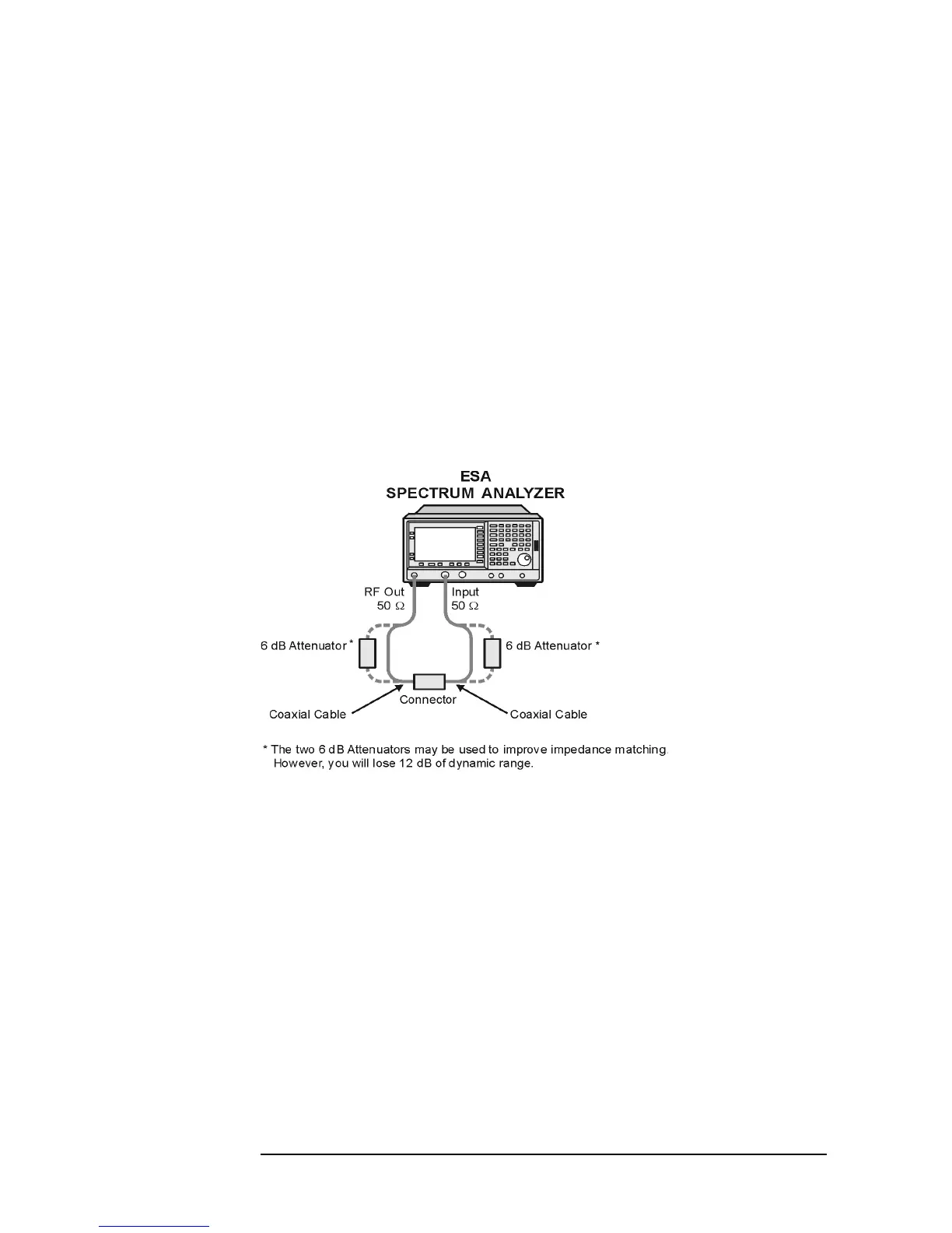
4. Establish a 0 dB reference trace for normalizing the measured data.
a. Remove the device from the measurement path and connect the
equipment as shown in Figure 5-8.
b. Press the
View/Trace front panel key.
c. Press the
More menu key.
d. Press the
Normalize menu key, Store Ref (1 - 3) and normalize On.
Figure 5-8 Calibrating the Analyzer for Loss/Gain Measurement
5. Make the measurement.
a. Re-connect the device.
Re-connect the tracking generator RF output to the device input
and the device output to the spectrum analyzer input as shown in
Figure 5-7 on page 5-13.
b. Read the measurement and save it if required.
Example
The following example measures the gain/loss of a bandpass filter
(BPF).
1. Adjust the spectrum analyzer control settings.
With the BPF in the measurement path, adjust the spectrum
analyzer control settings for the specific type of measurement to be