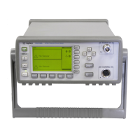
Agilent Technologies E4416A/E4417A Power Meters Service Guide xix
List of Figures
Figure 2-1 Zero Test Setup 19
Figure 2-2 Instrument Accuracy (Normal Path) Test Setup 22
Figure 2-3 Test Setup With Attenuator Connected 25
Figure 2-4 Instrument Accuracy (Average Path) Test Setup 29
Figure 2-5 Instrument Accuracy (Average Path) Test Setup 32
Figure 2-6 Power Reference Level Test Setup 38
Figure 2-7 Sensor (Average Path) Functional Test Setup 44
Figure 2-8 Sensor (Average Path) Functional Test Setup With Attenuator 45
Figure 2-9 Time Base Accuracy Test Setup 48
Figure 3-1 Adjustment Setup 62
Figure 3-2 A2L9 Adjustment Location 64
Figure 3-3 Adjustment Setup 66
Figure 3-4 A2R90 Adjustment Location 70
Figure 6-1 Troubleshooting Guide - TTL Output 1 118
Figure 6-2 Troubleshooting Guide - TTL Output 1 (continued) 119
Figure 6-3 Troubleshooting Guide - TTL Output 2 120
Figure 6-4 Troubleshooting Guide - TTL Output 2 (continued) 121
Figure 6-5 Troubleshooting Guide - TTL Inputs 122
Figure 6-6 Troubleshooting Guide - TTL Inputs (continued) 123
Figure 6-7 Troubleshooting Guide - TTL Inputs (continued) 124
Figure 6-8 Troubleshooting Guide - RS232/422 Interface 125
Figure C-1 Measurement Setup C-137
Artisan Technology Group - Quality Instrumentation ... Guaranteed | (888) 88-SOURCE | www.artisantg.com

 Loading...


