188 Chapter 8
Hardware Options
Overview and Verification of Option 123, Microwave and Millimeter Preselector Bypass
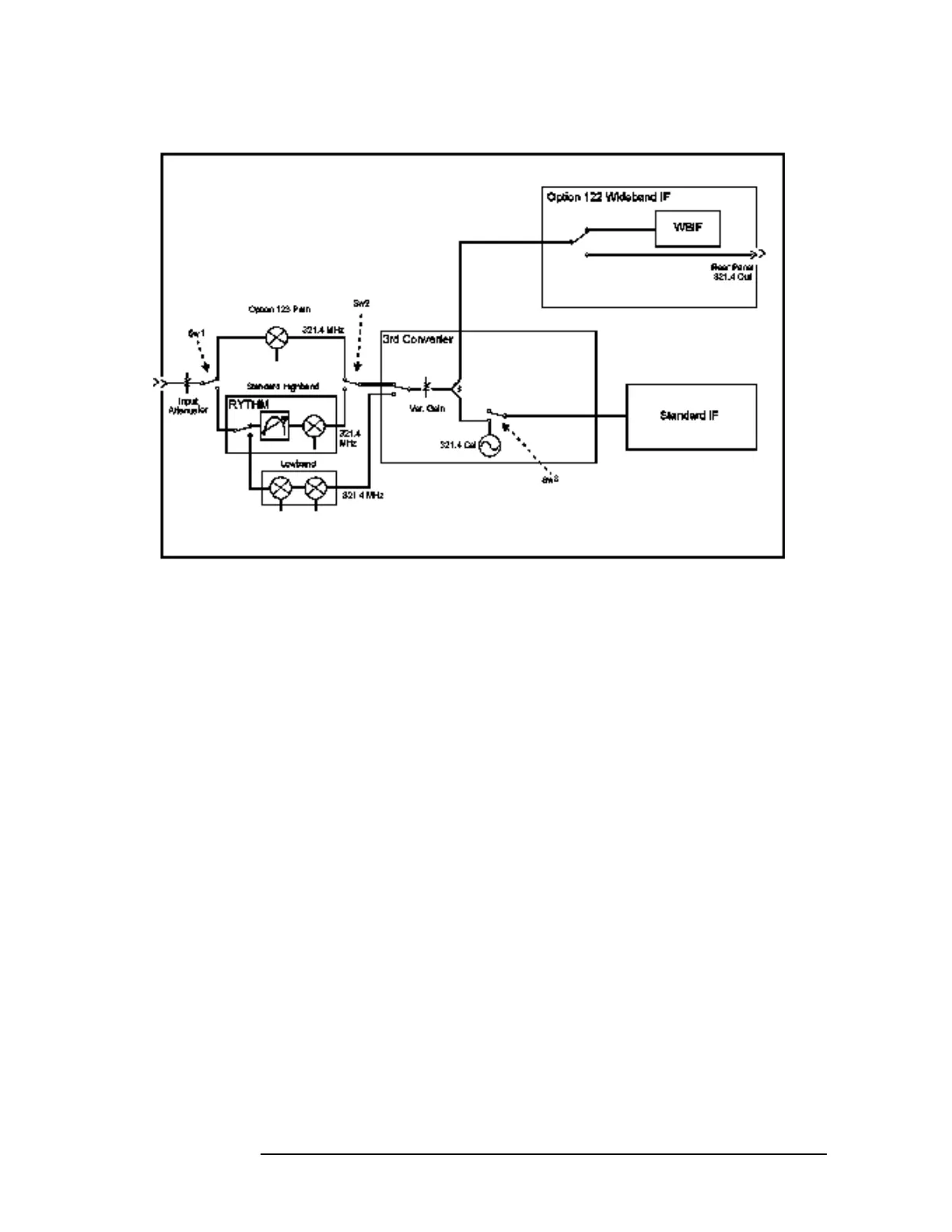
Figure 8-9 Block Diagram for DC to 26.5 GHz Option 123 Instruments
Figure 8-9 shows the block diagram of the instrument with an upper
frequency of 26.5 GHz. Functionally, Option 123 adds two new switches
(Sw1 and Sw2) into the signal path plus an additional mixer. In normal
operation above 3.05 GHz, Sw1 and Sw2 are in their down position,
which selects the signal path through the preselection filter. When the
unpreselected path is chosen, Sw1 and Sw2 are changed to their up
position, which bypasses the preselection filter.
When the instrument is operating below 3.05 GHz (Band 0), the signal
is routed to the Lowband circuitry. The lowband circuitry has built-in
low pass filtering so it does not require preselection. Please note that
the Lowband (Band 0) path is unavailable when switches Sw1 and Sw2
are configured for unpreselected operation. Furthermore, since these
are mechanical switches, it is unacceptable to switch them in the
middle of a sweep. Therefore when the unpreselected path is chosen,
Band 0 is locked out, and when any part of the sweep is in Band 0, the
unpreselected path is locked out.
 Loading...


