Service Guide E8364-90026 3-43
PNA Series Microwave Network Analyzers Tests and Adjustments
E8362B, E8363B, E8364B Adjustments
LO Power Adjustment
The LO power adjustment is used to adjust the power level of the LO signals from the A20
LO distribution assembly. This adjustment is done for only one LO output. The differences
between each LO output is negligible; therefore, separate adjustments are not required.
Equipment used for the LO Power Adjustment
Procedure
1. Turn off the network analyzer and remove the power cable and other external cables
from the rear panel.
2. Remove the outer cover. Refer to “Removing the Covers” on page 7-6.
3. Place the analyzer on its side to allow access to the bottom of the analyzer.
4. Connect the equipment as shown in Figure 3-19. Connect a GPIB cable between the
analyzer and the power meter.
5. With a 5/16-inch open-end wrench, loosen W40 at the first converter (mixer).
6. At the junction of W40 and W14, place a 5/16-inch wrench on the W40 connector and a
1/4-inch wrench on the W14 connector. While holding the 1/4-in wrench to prevent W14
from rotating, disconnect W40 from W14 and move W40 aside.
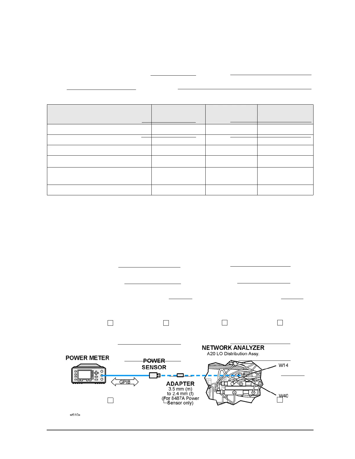
7. Connect the power sensor to the end of W14, as shown in Figure 3-19.
Figure 3-19 Setup for the LO Power Adjustment
Equipment Type
Models
Used With
Model or
Part Number
Alternate Model
or Part Number
Power meter All E4418B/E4419B E4418A/E4419A
Power sensor, 3.5 mm E8362B E4413A 8485A
Power sensor, 2.4 mm E8363B, E8364B 8487A None
Adapter, 2.4 mm (f) to 3.5 mm (m)
a
a. Required only if using the 8487A power sensor.
E8363B, E8364B 11901D None
5/16-inch, open-end torque wrench
(set to 10 in-lbs)
All N/A N/A
1/4-inch, open-end wrench All N/A N/A