Agilent InfinityLab LC Series Diode Array Detectors User Manual 196
12 Hardware Information
Interfaces
Special Interfaces
There is no special interface for this module.
ERI (Enhanced Remote Interface)
ERI replaces the AGP Remote Interface that is used in the HP
1090/1040/1050/1100 HPLC systems and Agilent 1100/1200/1200 Infinity
HPLC modules. All new InfinityLab LC Series products using the FUSION core
electronics use ERI. This interface is already used in the Agilent Universal
Interface Box 2 (UIB2)
ERI Description
The ERI interface contains eight individual programmable input/output pins. In
addition, it provides 24 V power and 5 V power and a serial data line to detect and
recognize further add-ons that could be connected to this interface. This way the
interface can support various additional devices like sensors, triggers (in and out)
and small controllers, etc.
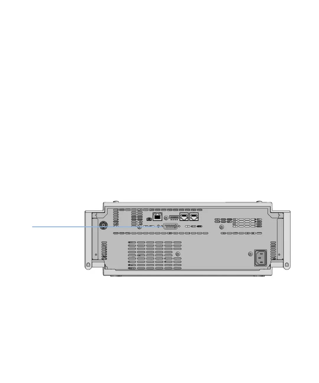
Figure 54 Location of the ERI interface (example shows a G7114A/B VWD)
 Loading...