Agilent InfinityLab LC Series Diode Array Detectors User Manual 199
12 Hardware Information
Setting the 6-bit Configuration Switch
Setting the 6-bit Configuration Switch
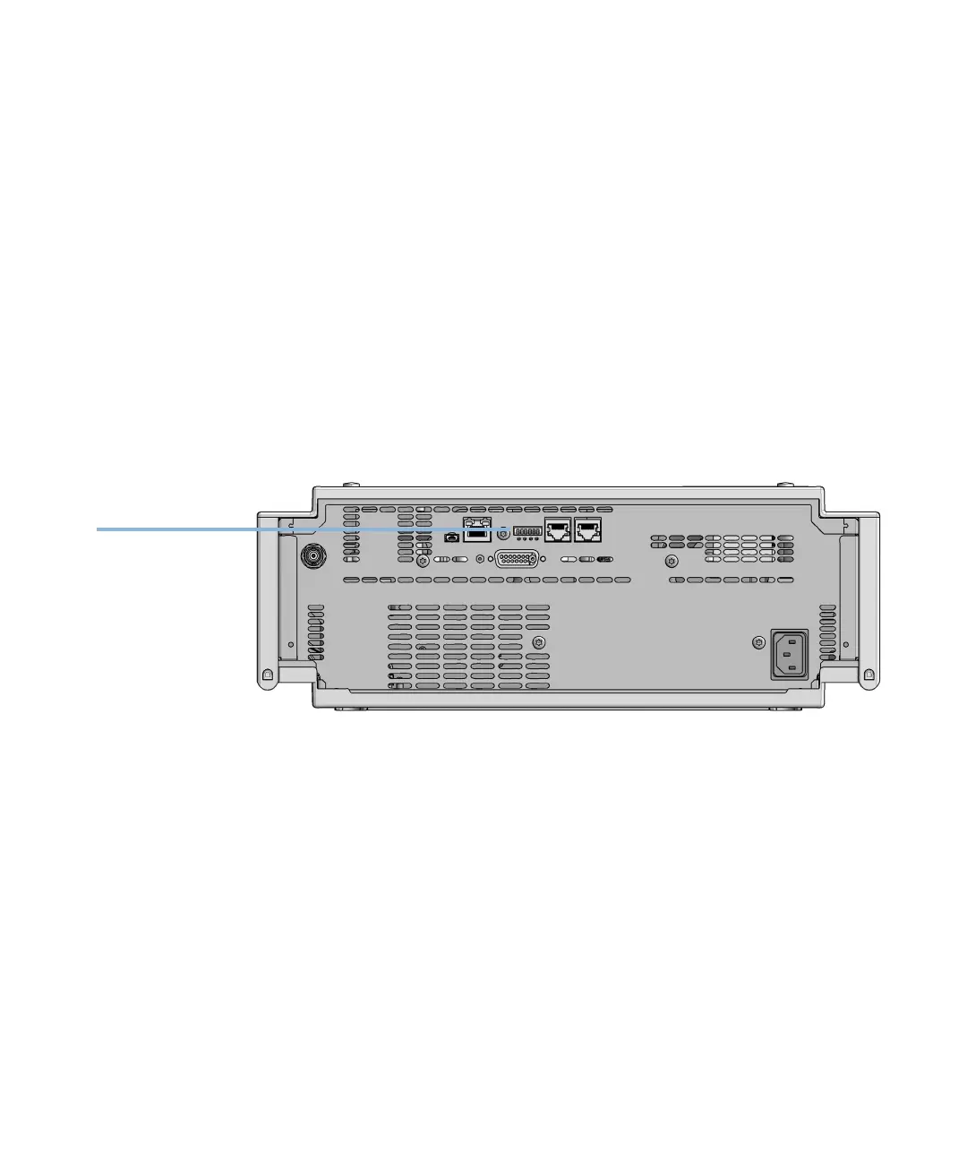
The 6-bit configuration switch is located at the rear of the module with FUSION
electronics. Switch settings provide configuration parameters for LAN and
instrument specific initialization procedures.
All modules with FUSION electronics:
• Default is ALL switches DOWN (best settings).
• Default IP address for LAN 192.168.254.11
• For specific LAN modes switches 4-5 must be set as required.
• For boot resident/cold start modes switches 1+2 or 6 must be UP.
Figure 55 Location of Configuration switch (example shows a G7114A/B VWD)
 Loading...