Installation
Connecting signal output cables
42
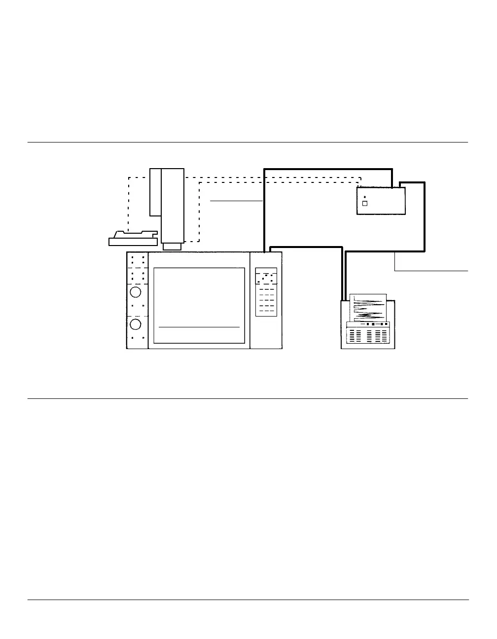
Each device to be included in INET communications is connected in
series with the next, forming a loop; thus, INET OUT on a given device
must be connected to INET IN on the next. The loop must be continuous,
and all devices must be on for the loop to function.
IN OUT
Controller
Sampler
5890
OUT
OUT
IN
IN
Controller & IntegratorHP 5890 SERIES II Gas Chromatograph
INET Cab
INET Cable
SERIES
II
Typical Inet Loop System
To install the INET communications cable:
1. Locate INSTRUMENT NETWORK IN (male) and OUT (female)
receptacles at the top of the HP 5890 (see the Locations for Signal
Cable Connections figure in this section).
2. Locate INET IN/OUT receptacles on other devices to be included in the
loop.
3. Install an INET cable between the OUT receptacle on the HP 5890
and the IN receptacle on the next device includedin the loop.
 Loading...