Installation
Connecting signal output cables
41
2. Connect lead cable(s) to the respective receiving device(s). If spade
lug•terminatedwires must be connected directly, note the following
with respect to color coding:
WHITE + (High)
BLACK - (Low)
ORANGE Ground
3. Lead the cable(s) out of the instrument at the rear of the signal cable
area. Replace the top panel (unless additional cables are to be
installed at this time).
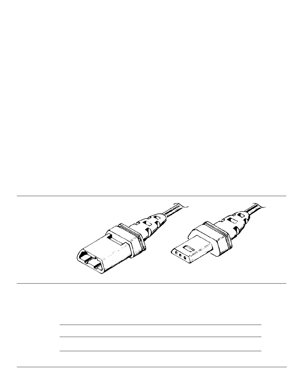
Instrument network (INET) cable
With Option 550 or 570 installed, the HP 5890 may be made part of an
Instrument Network (INET) system allowing automated operation of
the chromatograph, an integrator, an automatic liquid sampler, valves,
etc. The figure below shows the cable required to use this Option.
Inet Communications Cable
Note that two cables are always required to create a complete
communications loop.
Part No. Length Connector Type
82167D 5 m HP-IL
Available INET Communications Cables
 Loading...