Installation
Analog input board information
52
If an INET loop is to be used, install the loop cables. If an INET is not
being used, leave the INET cable between an in and out in place.
Connect the appropriate HP•IBor RS•232cable to the connector board.
Replace all of the instrument's panels and covers.
Analog input board information
Input Voltage -10mV to + 1V between + and - inputs
Input Noise 10
¿
V peak to peak
Input Common Mode
Range
+/- 5V DC (measured + or - to Gnd)
Common Mode Rejection
Ratio
80 db
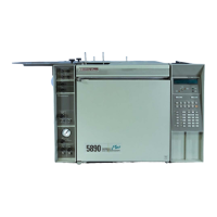
Scaling 1 HP 5890 display count + 16.2
¿
V input
At Range 6
1 mV input to board will produce a 1
mV output
Post-install checklist
U
Are the instrument supply gasses connected?
U
Have all the supply gas fittings been leak tested?
U
Have the signal output cables been connected?
U
Has the instrument power cord been connected?
Refer to the HP 5890 SERIES II Operating Manual for column
installation and operating information.

 Loading...


