Installation Note E4440-90613 15
Installation Procedure
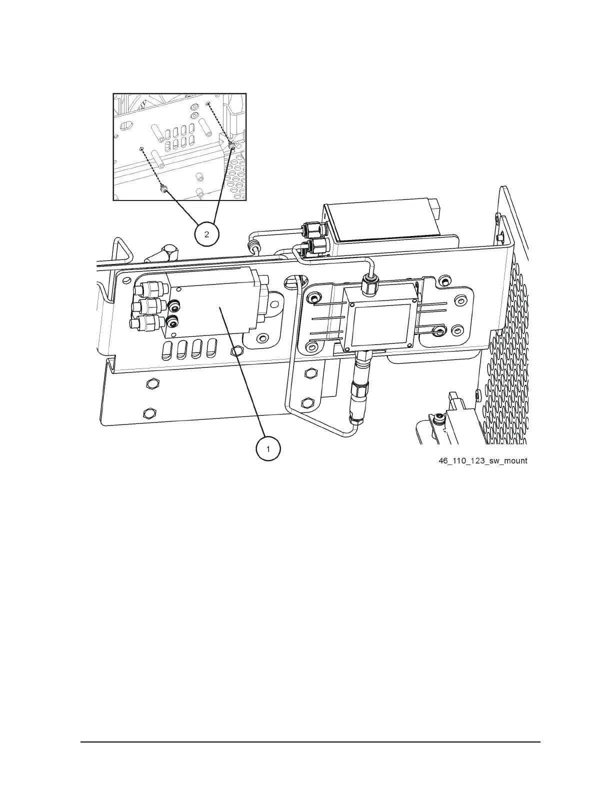
Figure 7 Coaxial Switch Assembly Installation
8. Refer to Figure 8. Remove the screw from the cable hold down rod on the mid web to
allow the “10” cable and other cables to be free.
9. In order to remove the RYTHM end of the cable, and replace the cable, several board
assemblies must be removed. Refer to Figure 8 and Figure 9. Please note the position
and routing of all cables. All of the flexible coax cables are color coded, but the ribbon
cables are not.

 Loading...


