Installation Note E4440-90613 41
Installation Procedure
7. Refer to Figure 34. Locate 1400-0611, PVC Cable Clamp. Stick Cable Clamp to the top
of the fan as shown and dress cables through the Cable Clamp as shown.
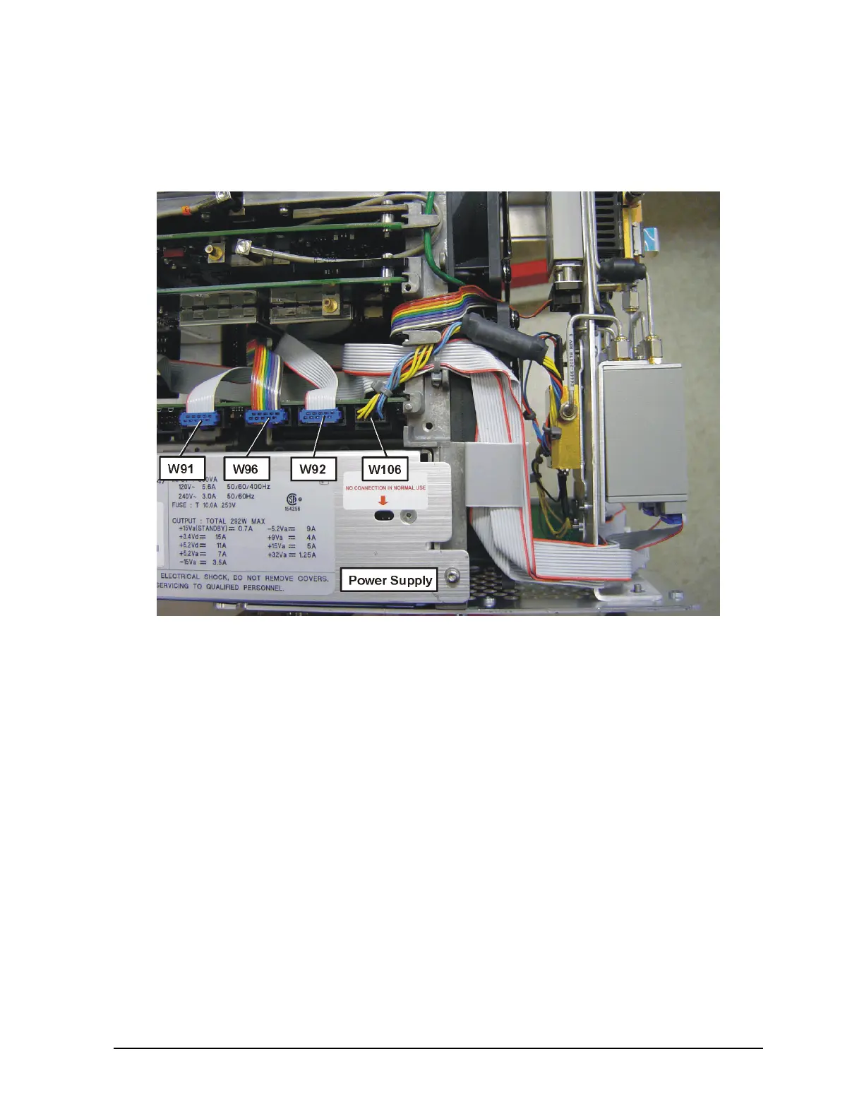
Figure 34 Option Driver Board Cables
Replace the Front Frame
1. Place the front frame assembly in front of the deck.
2. Connect the ribbon cable (3) to the A2 front panel interface board.
3. Feed the coaxial cable BNC connector through the
External Trigger Input hole in the
front frame, matching the “D” slot. Secure with the nut removed earlier, using a 9/16’”
socket. Torque to 21 inch pounds.
4. Clip the coaxial cable into the two cable clamps positioned on the front frame shield.
5. Position the front frame on the deck using the alignment bosses on the deck (5).
Remember to tuck the ribbon cable under the fans when pushing the frame onto the
deck. This will insure proper airflow to cool the instrument. Using the T-10 driver,
replace the 7 screws (1) that secure the front frame to the deck. Torque to 9 inch
pounds.

 Loading...


