Specifications 4
U1731B/U1732B User’s and Service Guide 31
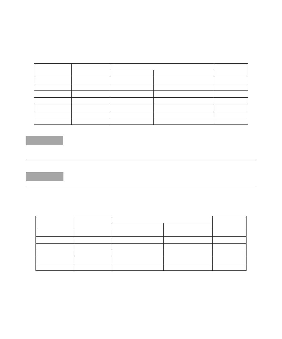
Capacitance (Parallel Mode), Test Frequency = 10 kHz
Inductance (Series mode), Test Frequency = 100 Hz/120 Hz
Range Maximum
Display
Accuracy Specified Note
Capacitance DF
50 µF 50.0 µF 3.0% + 8 (DF<0.1) 12.0% + 100/Cx + 10 (DF<0.1) After short cal.
20 µF 19.999 µF 3.0% + 6 (DF<0.2) 5.0% + 100/Cx + 8 (DF<0.2) After short cal.
2000 nF 1999.9 nF 1.5% + 5 (DF<0.5) 1.5% + 100/Cx + 6 (DF<0.5) -
200 nF 199.99 nF 1.5% + 5 (DF<0.5) 1.5% + 100/Cx + 6 (DF<0.5) -
20 nF 19.999 nF 1.5% + 5 (DF<0.5) 1.5% + 100/Cx + 6 (DF<0.5) -
2000 pF 1999.9 pF 2.0% + 6 (DF<0.5) 3.0% + 100/Cx + 6 (DF<0.1) After open cal.
200pF 199.99 pF 3.0% + 8 (DF<0.1) 5.0% + 100/Cx + 8 (DF<0.1) After open cal.
1 Q value is the reciprocal of DF.
2 This specification is based on the measurement performed at the test socket.
3 Device Under Test (DUT) and test leads need to be properly shielded to GUARD if necessary.
4 Cx = Counts of displayed C value, e.g. C = 88.88 µF then Cx = 8888.
It is recommended to set the test frequency to 1 kHz for a mult-layer ceramic capacitor of 10 μF
and below
Range Maximum
Display
Accuracy Specified Note
Inductance DF
1000 H 999.9 H 1.0% + (Lx/10000)% + 5 2.0% + 100/Lx + 5 After open cal.
200 H 199.99 H 0.7% + (Lx/10000)% + 5 1.2% + 100/Lx + 5 -
20 H 19.999 H 0.7% + (Lx/10000)% + 5 1.2% + 100/Lx + 5 -
2000 mH 1999.9 mH 0.7% + (Lx/10000)% + 5 1.2% + 100/Lx + 5 -
200 mH 199.99 mH 1.0% + (Lx/10000)% + 5 3.0% + 100/Lx + 5 After short cal.
20 mH 19.999 mH 2.0% + (Lx/10000)% + 5 10.0% + 100/Lx + 5 After short cal.
 Loading...