- 17 -
GT-DA-L/GT-DA
1
0
3
ON
1
23
4
CN
2
CN
1
6
CN2
CN1
CN2
CN1
CN2
CN1
CN2
CN1
CN2
CN1
8
9
GT-DA-L/GT-DA
1
0
3
ON
1
2
34
CN
2
CN
1
10
11
GT-SW
GT-AD
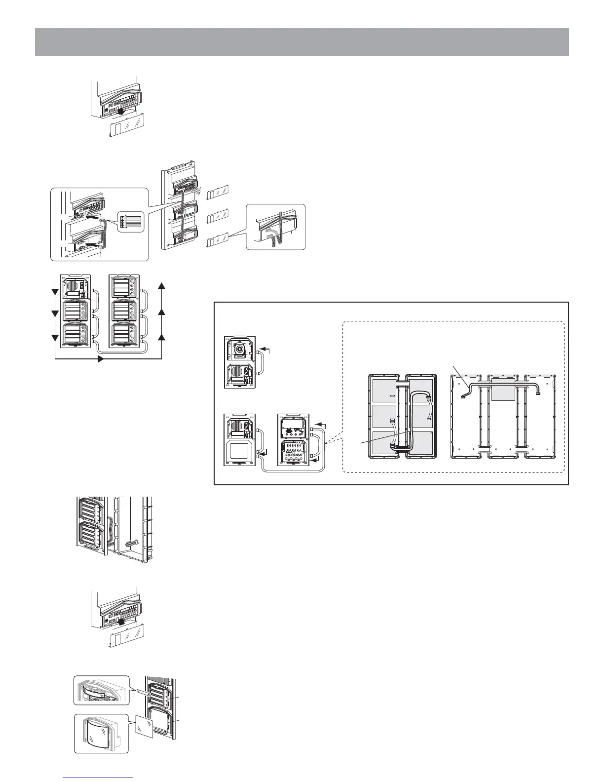
6 Remove the terminal cover.
8 Connect the connectors between the modules with cables.
Mount modules on the back boxes.
9 Run the connection cable through the joint pipe (which you should have made open in
advance) and connect CN1 of the GT-SW to the next row.
10 Put back the terminal cover.
Mount the front frame and tighten with the special screwdriver (enclosed with GT-
BC).
11 For the GT-SW and GT-AD, remove the resident name/address plate or paper by
pressing either the left or right end. (Peel off the plastic film.)
Use a permanent pen to write the resident name and address on the transparent plate
and mount the plate on the module.
1
0
3
O
N
1
2
3
4
O
N
O
N
1
2
GT-DA-L/GT-DA
GT-SW
1
0
3
ON
12
3
4
ON
CN1
CN2
7
7 From the speech module to the next module, insert the attached connector into the
socket.
Make sure to run the cable under the terminal cover for protection.
GF-C
GT-DA-L
/GT-DA
GT-AD GF-BP
GF-3B GF-3B
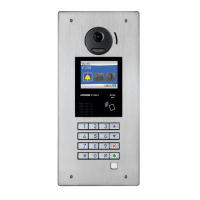
GT-10K
GT-VA
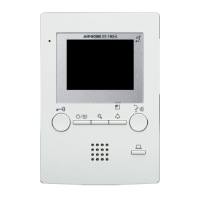
GT-NS-V
/GT-NS
GF-C
GT-DA-L
/GT-DA
GF-3B GF-3B GF-3B
CN3
CN1
GT-VA
GT-DA-L/GT-DA
CN1
CN3
CN100
CN2
CN1
CN2
GT-DA-L/GT-DA
GT-AD
GT-NS-V/GT-NS
GT-10K
Example of interconnection of modules
Use the GF-C to connect to the name scrolling module.
To position the speech module in the center row, run the
GF-C through the joint pipe in advance.