- 21 -
3
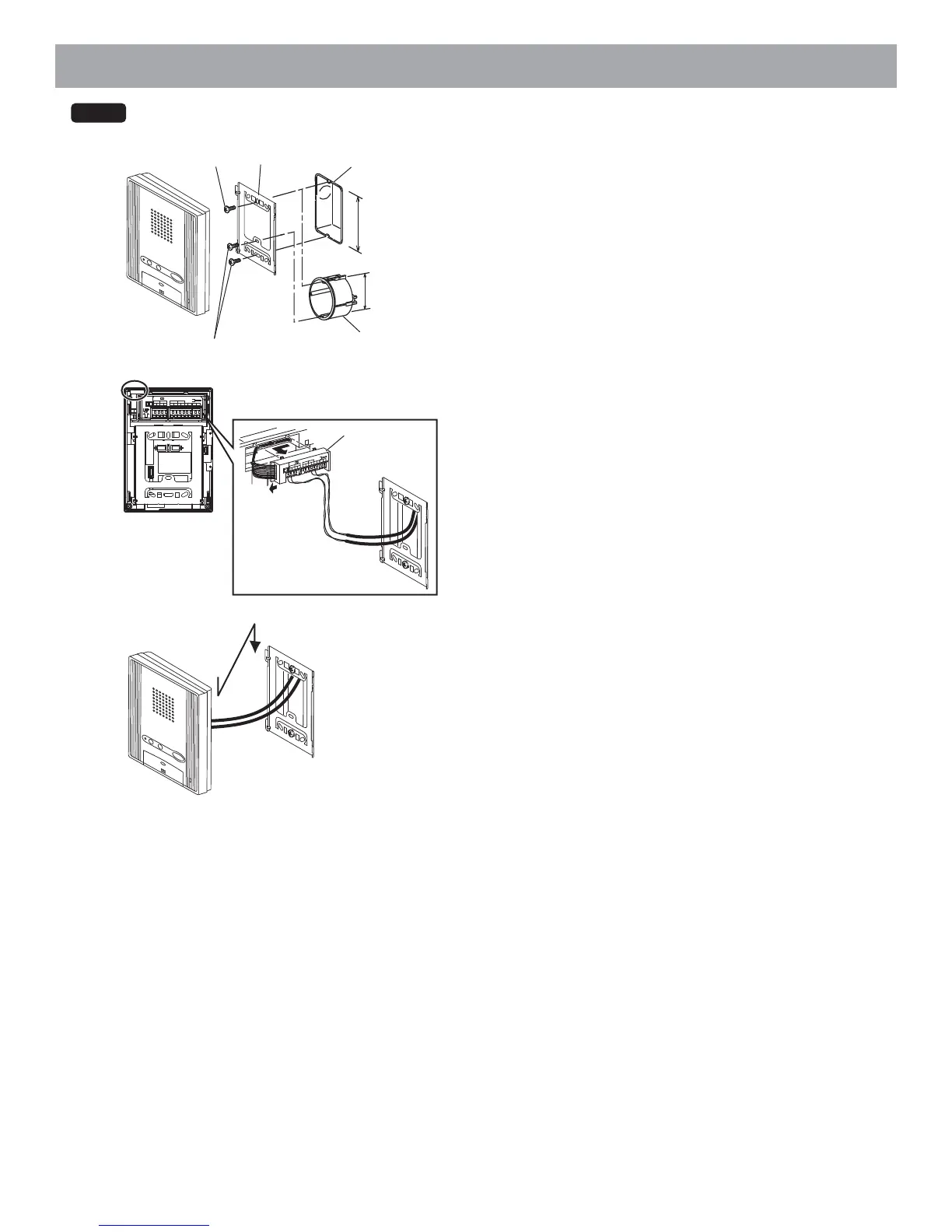
1 Mount the mounting bracket on the 1-gang box or round back box.
2 Connect the wiring to the terminal block.
• To remove the terminal block, slide the terminal block and pull it out.
• Strip away the jacket of the cable and insert all wires into the slots in an orderly
fashion. Failure to do so could result in pinching that may damage the wiring.
• For surface wiring, cut out the cable inlet.
3 Mount the station unit to the mounting bracket.
SW1 A B
IN OUT
R1 R2 R1 R2 C
0.6510 9
CE K KE
Donotremovethewires(Forendusers)
SW
1
AB
IN
OU
T
R1
R2
R1
R2
C
0.
651
0
9
CE
K
KE
Donotrem
o
vethewires
(Forendusers)
2
Terminal block
1
Mounting screws
Mounting bracket
Mounting screws
Round back box
1-gang box
83.5 mm (3-5/16")
OR
60 mm (2-3/8")
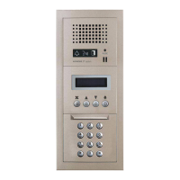
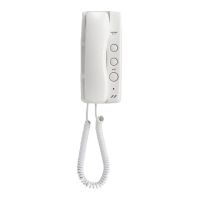
GT-1A