- 20 -
Surface wiring
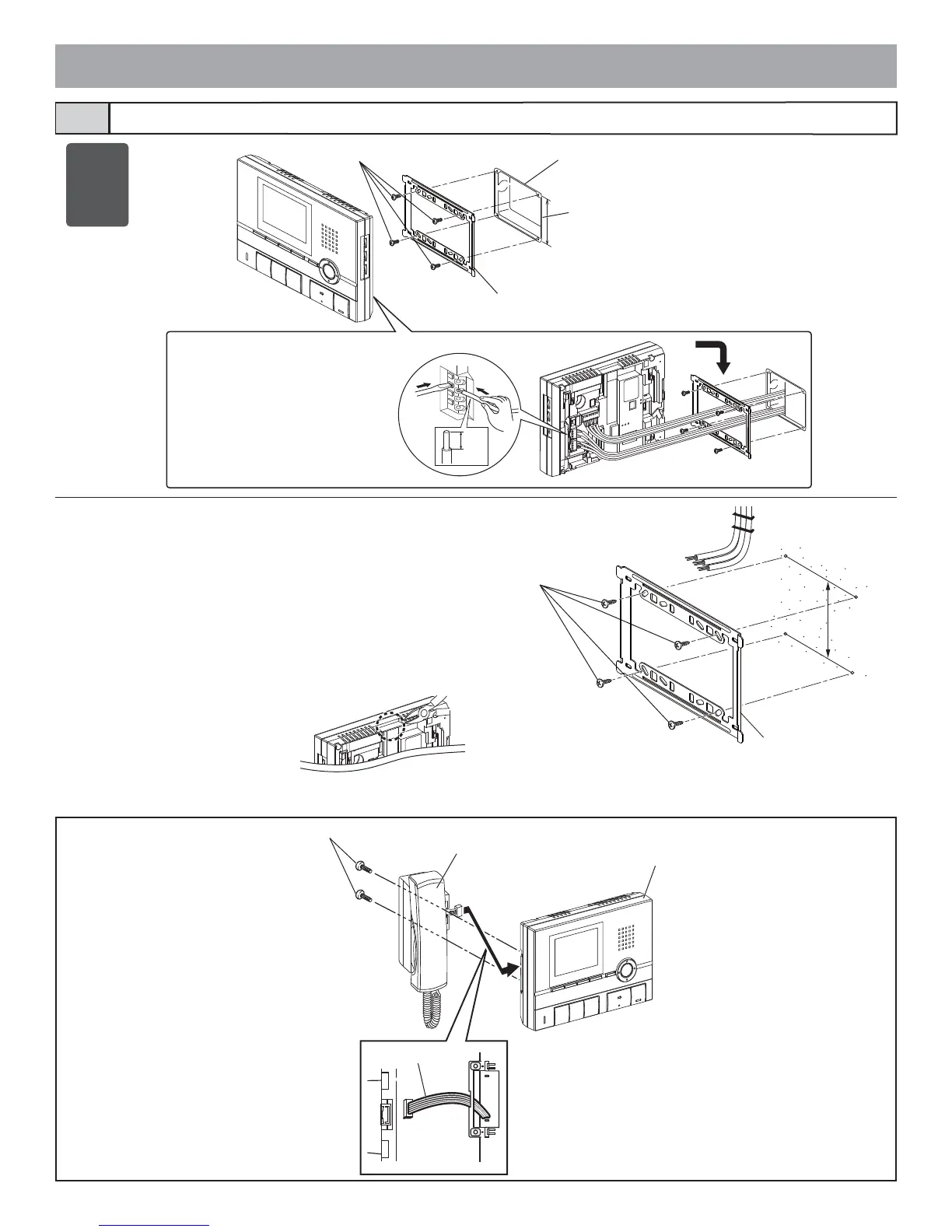
* When a 3-gang box is not mounted, the cable can be routed as surface
wiring to the top or bottom of the unit.
Cut a cable inlet on the upper part of the unit to allow passage of the
wiring into the unit.
If there is a large amount of wiring, strip away the jacket of the cable
up to the cable inlet.
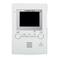
Residential station3-7
* To pass the cable through the back of
the unit, cut out the cable inlet.
Mounting screws ×4
Mounting bracket
83.5 mm
(3-5/16")
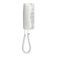
Optional handset
Screws (×2)
Handset GT-HS
Chassis
Station unit joint connector
Connect the station unit joint
connector.
GT-2C-L
GT-2C
GT-2H-L
GT-2H
GT-1C-L
GT-1C
1. Press the release button
(to insert or remove the wire).
2. Insert the cable into the terminal.
• To remove the terminal block, slide the
terminal block and pull it out.
• Strip away the jacket of the cable and in-
sert all wires into the slots in an orderly
fashion. Failure to do so could result in
pinching that may damage the wiring.
Mounting screws ×4
83.5 mm
(3-5/16")
Mounting bracket
1
2
8 mm
(3/8")
3-gang box