Page 101DD8
plus
Version 2.20 - September 1998
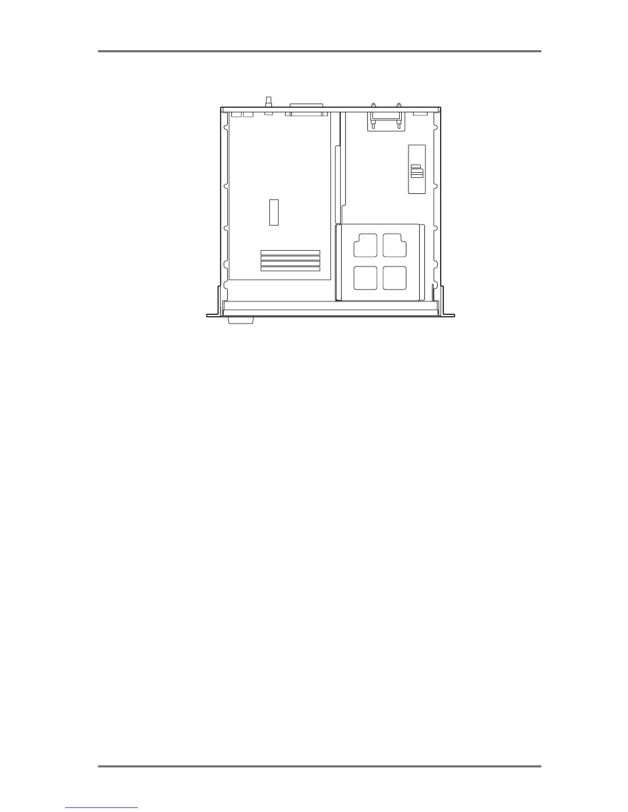
BOTTOM VIEW
INSTALLING IB-D8DA 8-CHANNEL ANALOG OUTPUT BOARD
The IB-D8DA 8-channel analog output board needs to be installed in the DD8 to allow use of
analog outputs.
Remove the connector cover for the analog output terminal (25-pin D-sub connector) by loosen-
ing the two screws on the rear panel. Place the IB-D8DA board in place (remove the two hex
screws on the D-sub connector first) and fix it with the four screws in the IB-D8DA package and
two hex screws on the connector. Connect the P5 (4-pin) cable from the Power Supply P.C.
Board to P3 (4-pin) and P2 (3-pin) cable on the IB-D8DA board to P6 (7-pin) on the Power P.C.
Board. Then securely connect the far end of the 60-pin AD/DA cable (included with the DD8 in a
separate package) between P1 on the IB-D8DA board and P103 on the CPU P.C. Board (lo-
cated underneath the unit). Tie the cable with the tie-band (included with the DD8 in a separate
package) to the chassis.
If the IB-D8AD 8-channel analog input board is installed at the same time, use the second
connector instead of the first one of the 60-pin AD/DA cable. The same 60-pin cable is used for
both the IB-D8AD and IB-D8DA boards.
INSTALLING IB-D8AD 8-CHANNEL ANALOG INPUT BOARD
The IB-D8AD8-channel analog input board needs to be installed on the DD8 to input analog
signals.
Remove the connector cover for analog input terminal (25-pin D-sub connector) by loosening
the two screws on the rear panel. Place the IB-D8AD board in place (remove the two hex screws
on the D-sub connector first) and fix it with the four screws in the IB-D8AD package and two hex
screws on the connector. Connect the P2 (7-pin) cable on the IB-D8AD board to P7 (7-pin) on
the Power Supply P.C. Board. Then securely connect the far end of the 60-pin AD/DA cable
(included with the DD8 in a separate package) between P1 on the IB-D8AD board and P103 on
the CPU P.C. Board (located underneath the unit). Tie the cable with the tie-band (included with
the DD8 in a separate package) to the chassis.
If the IB-D8DA 8-channel analog output board is installed at the same time, use the second
connector for the IB-D8DA board. The same 60-pin cable is used for both the IB-D8AD and IB-
D8DA boards.
APPENDIX - 2