Page 6 DD8
plus
Version 2.20 - September 1998
INTRODUCTION - 1
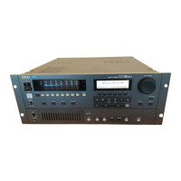
FRONT PANEL
Next to the Power Switch, the 8 LED barmeter displays are used as peak level meters as well as
indicating the track’s status:
ACTIVE Audio data being played from disk.
TRK SLIP Audio track slipped in time from its original location.
The W/C RCV LED is used to indicate the status of the external word clock input. When external
sync is selected, this indicator will light steadily when the correct word clock signal is being
received. If there is a problem with the word clock signal, this LED will flash.
Similarly, the T/C RCV LED is used to indicate the status of the external timecode input. When
external timecode is being received successfully, the DD8 will play synchronised to that timecode
and the T/C RCV LED will be steadily lit. If at any time, the T/C RCV LED flickers, this indicates
a problem with the external timecode such as dropout. The DD8 will ‘flywheel’ for a short while in
the event of timecode dropout but, if the dropout is too long, the DD8 will stop playing.
Under the power switch, the PANEL ENABLE/DISABLED switch is used to lock the keys on the
front panel to prevent accidental operation.
The PLAY, RECORD, NUDGE and TRACK SLIP keys are used to select one of the DD8’s
‘PROJECT’ modes, and also determine the current function of the track select keys (1~8 and
ALL).
In the ‘PROJECT’ modes, the track select keys (1~8, ALL) are used for selecting tracks. They
can also be used in some of the setup pages as a numeric keypad. In this situation, the ALL key
is used as ‘0’ and the SYNC key is used as ‘9’.
Under the LCD display are 6 soft keys (F1 ~ F6) used to select items on the LCD.
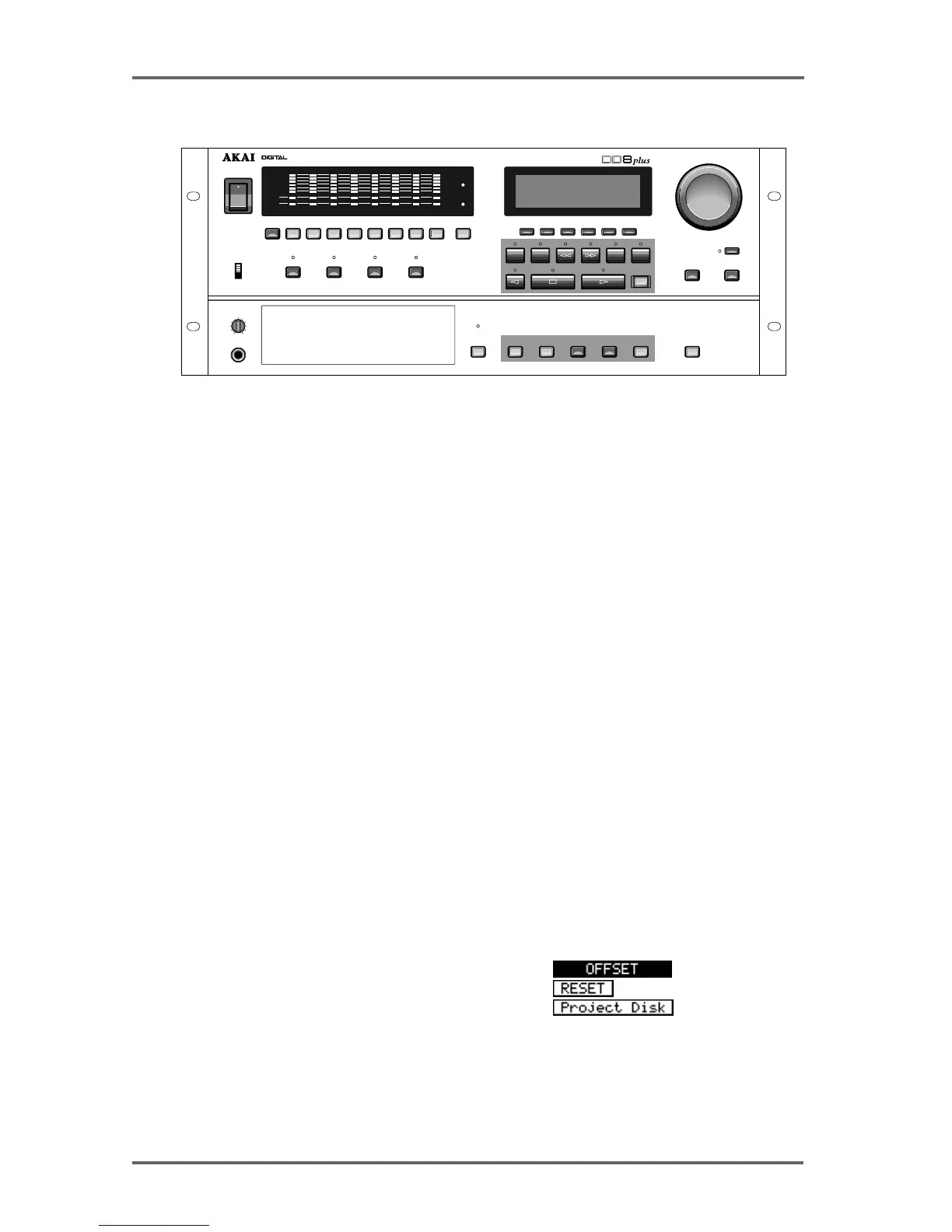
The type of action performed when one of the soft keys is pressed is indicated by the style of the
soft key display shown on the bottom line of the LCD:
• Accessing another page
• Executing a function
• Moving the cursor to the indicated field
PLAY RECORD NUDGE TRACK SLIP
PANEL
ENABLED
DISABLED
LEVEL
MIN
MAX
PHONES
DISK
DISK BUSY
SYSTEMSTOREGO TO ENTER ESCAPE UNDO
F
1
F
2
F
3
F
4
F
5
F
6
REC
START
END
JOG / SPOOL
DATA
+
JOG / SPOOL
DATA
–
ON
OFF
POWER
1 2 3 4 5 6 7 8 9 / SYNCALL / 0
DIGITAL DUBBER
ACTIVE
TRK SLIP
CLIP
REF
CLIP
REF
W/C
RCV
T/C
RCV
12345678
CYCLE TO FROM
IN
->
OUT