,---
I
I
I
PHI-I
I
I
I
I
I
PHI
I
I
I
I
I
I
L----l
Counter
10
11
3:
20
Indication 7
11
0:50
H
L
L
H
FR3
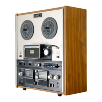
When
the switch
of
PHl-2
is
ON,
the gate
of
SCR2
becomes
"L"
and
SCR2
is
turned OFF.
When
SCR2
is
OFF, no current will run to
Rl32
and there
will
be
no potential difference
between the gate and the anode
of
SCR4
(triode
AC
switch), and therefore
it
will
be
OFF.
On
the other hand,
since
PHl-1
is
OFF,
SCRl will
be
ON
and
SCR3
ON.
This means
that FR2 39 ohms, instead
of
Rl
24
36 ohms,
is
connected in parallel to the take up reel motor
and the
RWD
mode
is
maintained. Now, the
signal
of
IC2
@
is
considered.
IC2
@ (in-
terrupt)
rec.eives
the
signal
(input to real time
counter) from the Detecter
P.C
Board. The
counter starts counting the input
signal
of
@
every
25
msec
from 0:00:50. This data
is
com-
0
RL0-1
Take-up
@
®
Supply
Fig.
645
AC
Rl24 36
Take-up
@
@
Fig.
644
0
I
I
I
1c-2@ Output waveforms
Fig.
646
pared with the data written in IC2
and
when
the reel motor
is
running at a speed faster than
the data,
"H''
signal
is
issued to @.
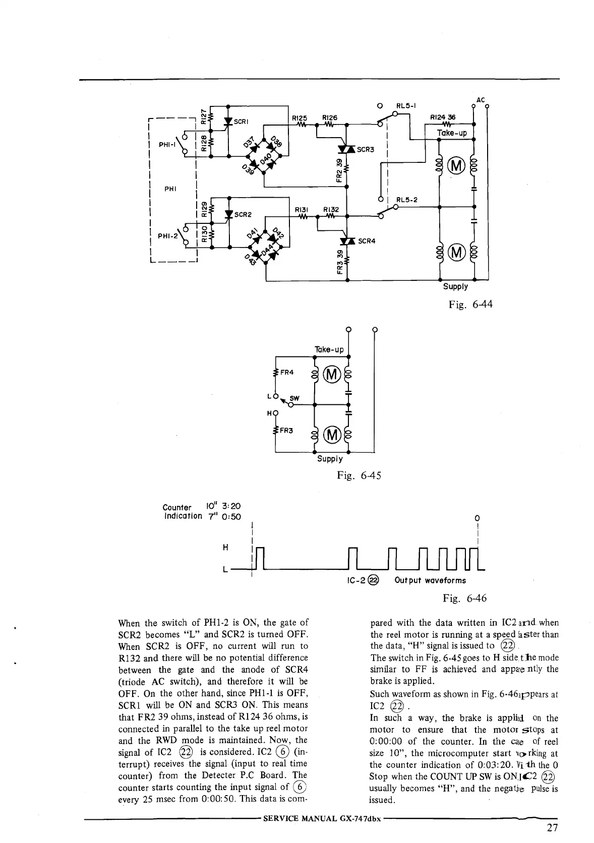
The switch in Fig. 6-45
goes
to H
side,
t:he
mode
similar to FF
is
achieved and apparently the
brake
is
applied.
Such waveform
as
shown in Fig. 6-46appears at
IC2
@.
In such a way, the brake
is
applied
on
the
motor to ensure that the motor
stops at
0:00:00
of
the counter. In the
caie
of
reel
size
1
O",
the microcomputer start 'It>
rking
at
the counter indication
of
0:03:20.
li
1h
the
0
Stop when the
COUNT
UP
SW
is
ON,1£2 @
usually becomes
"H",
and the negatite
pulse
is
issued.
---------------SERVICE
MANUAL
GX-747dbx---------------
27
 Loading...