10
within a wooden frame and are based on 100 mm.
Acoustic modules. The attenuators should be fitted
with weather louvers with a minimum 50 % free area,
good airflow profile and afford l
ow restriction airflow access.85dB(A) noise level at 1
m will be obtained by using noise level attenuators in
order to meet EEC standard regulation .if you want to
decrease the noise level more than that ,increase the
length of the attenuators.
The weather louvers should have bird/vermin mesh
screens fitted on the inside, but these screens must
not impede the free flow of cooling and aspiration air.
The outlet attenuator should be connected to the ra-
diator ducting flange with a heat and oil resistant flex-
ible connection.
Combustion Air Inlet
Air for engine combustion must be clean and as cool
as possible. Normally this air can be drawn from the
area
surrounding the generating set via the engine mounted
air filter. However, in some cases due to dust, dirt
or heat the air around the set is unsuitable. In these
cases an inlet duct should be fitted. This duct should
run from the source of clean air (outside the building,
another room, etc) to the engine mounted air filter
Exhaust systems
The exhaust systems shown on the layout drawings
are supported from the ceiling. Should the building
construction be such that the roof supports were
unable to support the exhaust system, a floor stand-
ing steel exhaust stand will be needed. Exhaust pipes
should terminate at least 2,3 m above floor level to
make it reasonable safe for anyone passing or acciden-
tally touching. It is recommended that stainless steel
bellows be fitted to the engine exhaust manifold fol-
lowed by rigid pipe work to the silencer. It is good
installation practice for the exhaust system within the
generator room to be insulated with a minimum of 50
mm. of high density, high temperature mineral insula-
tion covered by an aluminium over clad. This reduced
the possibility of operator burn injury and reduces the
heat being radiated to the operating generator room.
Cooling and Ventilation
The engine, alternator and exhaust piping radiate heat
which can result in a temperature high enough to ad-
versely affect the performance of the generator set. It
is therefore important that adequate ventilation is pro-
vided to keep the engine and alternator cool. Proper
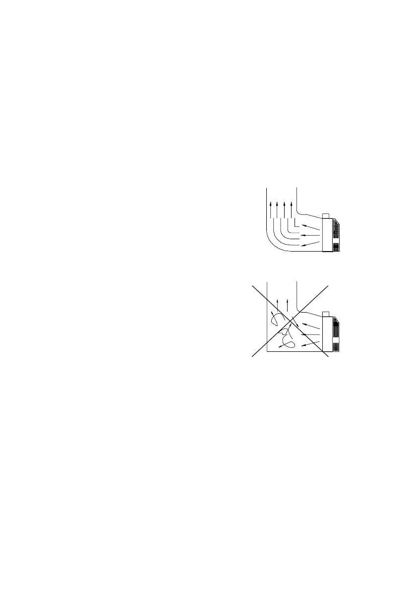
air flow, as shown in Figure 5.4. requires that the air
comes in at the alternator end of the set, passes over
the engine, through the radiator and out of the room
via a flexible exhaust duct. Without the ducting of the
hot air outside the room, the fan will tend to draw that
hot air around and back through the radiator, reducing
the cooling effectiveness.
Figure 5.3. Directing the air thrown from the radiator
with deviating wings.
Figure 5.4. Weak ventilation
Sharp corners on the radiator hot air outlet or its chim-
ney must be avoided. some rearrangements should be
done to change the direction of the air comes out of
radiator.
The air inlet and outlet openings should be large
enough to ensure free flow of air into and out of the
room. As rough guide the openings should each be
at least 1,5 times the area of the radiator core. Both
the inlet and outlet openings should have louvers for
weather protection.