11
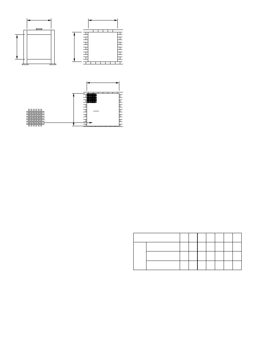
Figure 5.5. Air Inlet and Outlet Area
These may be fixed but preferably should be movable
in cold climates so that while the generator set is not
operating the louvers can be closed. This will allow
the room to be kept warm which will assist starting
and load
acceptance for automatic starting generator sets. If the
louvers are movable they must be automatically oper-
ated. They
should be programmed to open immediately upon
starting the engine.
5.4. Essential Circuits
As a generator owner, it is important that you clearly
identify the circuits in your building that are “essential”
to you. It is also important that your installer under-
stand which circuits you want to include as “Essen-
tial Circuits”. Depending on the power consumed by
these circuits, most or all of them can be switched to
the home generator for the duration of normal power
interruption.
Essential Circuit Selection
When selecting the essential circuits that will be
switched to “Standby Power,” it is important that the
sum of the combined circuit loads does not exceed
the wattage/amperage capacity of the generator. To
help you with your selection of essential circuits, please
consider the following:
• Add up the total wattage of all electrical devices to
be connected at one time, This total should NOT be
greater than the generator’s wattage capacity.
• Some electric motors (induction types) require
about three times more watts of power for starting
than for running. This surge lasts for only a few sec-
onds. Be sure you allow for this high starting wattage
when selecting electrical devices that will be energized
by the generator:
• Figure the watts required to start the largest motor,
o Add that to the total running watts of all other con-
nected loads.
The choice of the electric cables
The choice of the electric cable depends on the allow-
able current of the cable and the distance between the
load and the generator. And the cable section should
be big enough.
If the current in the cable is bigger than the allowable
current, it will become overheated and the cable will
be burnt.
If the cable is long and thin, the input voltage of the
electric appliance will be not enough, causing that the
generator doesn’t start. The following table indicates
the maximum allowable 3-phase current (in A), in an
ambient of 40°C,
Table 5.1. Essential Circuits
6. PREPARATORY STEPS FOR OPERATION
6.1 Preparation of Fuel
Use recommended fuel only. Fuel standard could be
different from country to country. Some of them are
mentioned below.
ISO8712DMA
ASTMD975 Grade No:1-D or No:2-D
GB/T252-1994 Grade No:0 in summer , Grade No:-
1.2m
1.44m
2
1.2m
Radiator matrix
frontal area
1.34m
1.34m
1.44m
2
+ 25%
=1.80m
2
Air outlet or inlet
= 2.25m
2
1.8
0.8
1.5m
Air outlet or inlet
size to allow for
grille
Grille 80%
free area
Free Flow Area
1.5m
Wire Section (mm
2
)
Multiple core
Single core
H07 RN-F
Max.
Cuurent (A)
2,5
22
25
21
4
30
33
28
6
38
42
36
10
53
57
50
16
71
76
67
25
94
101
88
35
114
123
110