6
• When breathing restarts, place the victim into the
recovery position described later in this section.
If no breathing and no pulse
• Call or telephone for medical help.
• Give two breaths and start chest
compression as follows.
• Place heel of hand 2 fingers breadth above ribcage/
breastbone junction.
• Place other hand on top and interlock fingers.
• Keeping arms straight, press down 4-5 cm at a rate
of 15 times per minute.
• Repeat cycle (2 breaths and 15 compressions) until
medical helps takes over.
• If condition improves, confirm pulse
and continue with breaths. Check for
pulse after every 10 breaths.
• When breathing restarts, place the victim into the
recovery position described below.
Recovery position
• Turn the victim onto the side.
• Keep the head tilted with the jaw forward to main-
tain the open airway.
• Make sure the victim cannot roll forwards or back-
wards.
• Check for breathing and pulse regularly. If either
stops, proceed as above.
Warning
• Do not give liquids until victim is conscious.
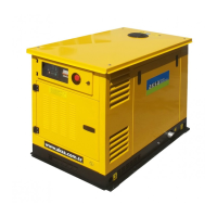
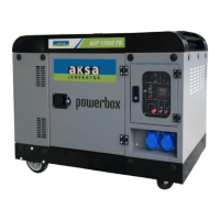
3. GENERAL DECRIPTION;
3.1. Generator Set Description and Identification
Diesel –electric generator sets are independent units
for the production of electric power; basically, they
comprise a constant voltage synchronous generator
driven by an internal –combustion, diesel – four cycle
engine.
The sets are used for two main purposes:
a-Continuous duty sets;
Used to produce electric power for countless require-
ments (motive power, lighting, heating, etc) in areas
where other sources or power are unavailable.
b-Emergency duty sets;
Used during public network failures, when such failures
are liable to cause serious trouble to persons or mate-
rial or financial damage (i.e. in hospitals, industrial plants
with non-stop operating cycles, etc) or to meet peak
energy demands.
According to their application, the sets are further di-
vided into:
-Set for use on land,
-Set for use at sea,
The sets for use on land can be either:
-Stationary sets (fixed installation), or
-Mobile sets (mobile installation)
These two types of sets are available in a vast range
of versions, for every operating requirement, the main
ones being:
01. Hand control generator sets,
02. Stand-by generator sets,
Aksa Generator Set has been designed as a complete
package to provide superior performance and reliabil-
ity.
Figure identifies the major components. This figure3.1.
is of a typical generating set. However, every set will
be slightly different due to the size and configuration of
the major components. This section briefly describes
the parts of the generating set. Further information is
provided in later sections of this manual.
Each generating set is provided with a Rating Label
(Item 1) generally fixed to the base frame. This label
contains the information needed to identify the gener-
ating set and its operating characteristics. This informa-
tion includes the model number, serial number, output
characteristics such as voltage and frequency, output
rating in kVA and kW, product date and weight.
The model and serial numbers uniquely identify the
generating set and are needed when ordering spare
parts or obtaining service or warranty work for the set.
Aksa generating sets are an Alternating Current gen-
erator, built for continuous running at sites where no
electricity is available (some models are excepted) or
as stand-by in case of interruption of the mains.
Aksa generating sets are an Alternating Current gen-
erator, built for continuous running at sites where no
electricity is available (some models are excepted) or