10 albinpump@irco.com Albinpump.com Albin Pump ALH Instruction Manual
since 1928
ALH
Installation
DIMENSIONS
mm (Inch)
4 | INSTALLATION
4.1 - UNPACKING AND CONTROL
During the receipt of the pump, please follow the instructions printed on the packing. Make a visual inspection to insure that no
damage occurred during shipment. If this is the case, please contact your ALBIN PUMP distributor as soon as possible.
4.2 - CONDITIONS OF USE
ALH pumps can work in atmospheres where the temperature is situated between -20°C (-4°F) and 45°C (113°F). Pumps are
coated with a 150µ paint which will protect them against certain aggressive environments. They are designed for indoor and
outdoor setup.
4.3 - SET UP
Before installing the pump, check the following points:
- The pump is delivered with a frame provided with four anchoring holes. It must be xed on a solid base with a slope which
does not exceed 5mm for 1m and must be rmly fastened to this one.
- Require enough space around the pump to carry out maintenance. If such was not possible, consider the moving of the pump
to a space provided for this purpose.
- Make sure that the room is adequately ventilated to relieve the heat generated by the pump. Leave a space behind the motor
ventilator hood so as not to obstruct air intake.
4.4 - PIPING
Suction line piping:
- The internal diameter of the piping must be equal to or greater than that of the pump hose,.
- It must be the shortest and most direct possible to avoid suction loss.
- Suction pressures at higher operating pressures may cause the pump to rotate when the pump is disengaged. Above 1 bar,
consider adding a suction line valve to prevent this occurrence.
- Limit the presence of bends and make sure that they are as large as possible.
- Make sure that piping can support the service pressure of the pump.
Discharge line piping:
-The internal diameter of piping must be equal to or greater than to that of the pump hose, see §3.4.
- It must be the shortest and most direct possible to avoid discharge pressure loss.
- Limit the presence of bends and make sure that they are as large as possible.
- Provide a space for a pulsation dampener (see picture below).
- If there is a valve on the discharge line, install a pressure relief valve or an over pressure protection gauge to avoid any
possible damage to the pump and to the installation.
- It is recommended to install a exible line to help absorb pulsation.
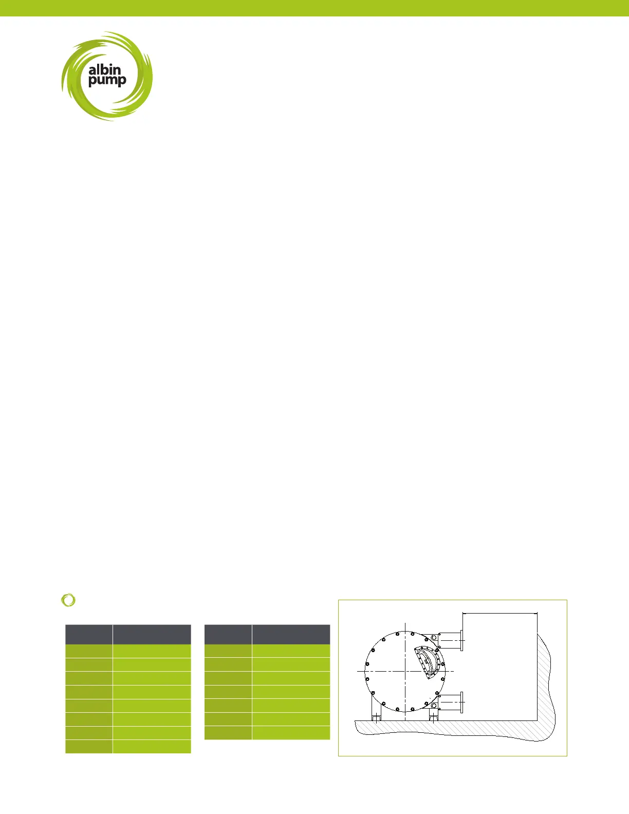
During the pump ground study, provide enough space for the hose change as well as the possible installation of a pulsation
dampener. Distance (L) is the required length for hose removal.
PUMP L
ALH05 400 (15.7)
ALH10 400 (15.7)
ALH15 500 (19.7)
ALH20 500 (19.7)
ALH25 800 (31.5)
ALH32 1000 (39.4)
ALH40 1000 (39.4)
ALHX40 1200 (47.2)
PUMP L
ALH50 1400 (55.1)
ALH65 1400 (55.1)
ALHX65 1500 (59.0)
ALHX80 1600 (63.0)
ALH80 2000 (78.7)
ALH100 2800 (110.2)
ALH125 3000 (118.1)