Albin Pump ALH Instruction Manual Albinpump.com albinpump@irco.com 23
since 1928
ALH
Maintenance / Storage
6.7 - ALHS SERIES INFORMATION
6.7.1 - SET UP
Before the setup of the pump, check the following points:
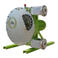
- The ALHS pump is delivered without a frame. Assembly holes are at the back of the pump for as-
sembly on a frame. Dimensions of these assembly holes can be found in § 9.2. The pump with its
drive and frame must be xed to a solid base with a slope which does not exceed 5mm for 1m and
must be rmly fastened to this one.
- The pump frame must be built in order to support the stress and deformations delivered by the
pump and drive. It should be built by qualied sta with good engineering practice. In no case
ALBIN PUMP is responsible for it’s construction or conception.
- The alignment of pump and drive shafts must be made in accordance with instructions given by the
manufacturer of the coupling. Refer to the specic notice of such material. To achieve alignment and
coupling, use a perfectly straight ruler to control the misalignment, and a feeler gauge for angular
misalignment. Control four points (top, bottom, left, right) at each stage of the installation (after set-
ting on foundations, after xing pipes and after a rst start).
- Make sure there is enough room around the pump to carry out maintenance. If that was not the
case, envisage the moving of the pump in a space provided for this purpose.
- Make sure the room is adequately ventilated to relieve the heat generated by the pump. Leave a
space behind the motor ventilator hood so as not to obstruct the air intake.
6.7.2 - PUMP STARTING
Follow the steps described in §5. The hose is not mounted on bare shaft pumps when delivered.
Therefore, hose mounting operations should be followed before the starting up.
6.7.3 - BEARING CASE DISMANTLING AND LIP SEAL (REF 26) REPLACEMENT
Carry out operations described in §6.4.2 Disassemble the bearing case in the same way as for the
gearbox.
1 - Remove lip seals (REF 105) and REF 106 from the bearing case.
2 - Remove the circlips (REF 107).
3 - Remove the shaft with the bearings.
4 - Carry out the disassembly of the bearings and replace them together with the shaft (REF 102) if
necessary.
5 - Remove the shaft and the bearings, circlips and O-rings. Fill up the bearing box with grease
through the greaser positioned on the top of the box.
6.7.4 - MAINTENANCE AND PERIODICAL CONTROLS
Regularly check the absence of grease coming from the leakage channel or from the lip seal (REF 106).
7 | STORAGE
7.1 - STORAGE OF THE PUMP
Store the pump in a sheltered and dry place and ensure that the storage room temperature is be-
tween -20°C (-4°F) and 45°C (113°F). Protect the pump if necessary and block the inlet and outlet
orices. If pump remains idle for over 1 month, remove the hose from the pump or remove one of the
shoes as well as its centering pin and position the wheel so that the second shoe can be seen through
the sight glass. For models ALH05, ALH10, ALH15 and ALH20 position the wheel so that one of the
cam lobes remains submerged in the lubricant. If you can neither withdraw the hose or one of the
shoes, run the pump 5 minutes a week.