Albin Pump ALH Instruction Manual Albinpump.com albinpump@irco.com 11
since 1928
ALH
Installation / Pump Start-up / Maintenance
5 | PUMP START-UP
5.1 - PREPARATIONS
a. Connect the electrical motor in accordance with the local rules and regulations. Perform this work by qualied personnel.
b. Make sure that the lubricant level arrives at the level of the sight glass (see §9.7 for lubricant table and §6.1 for an
image). Add lubricant if required by the breather or by the sight glass, see §6.1 for instructions on emptying and lling
the lubricant.
c. Make sure the shimming of the pump is according to the pump process, see §6.5 shoe shimming. Refer
to §9.8 for shoe shimming tables.
d. Check the direction of rotation of the pump. It is recommended to install a rotation inverter on the motor for the hose
change.
5.2 - START-UP
a. Install piping at the inlet and outlet of the pump.
b. Make sure that valves at the inlet and outlet are opened.
c. Start the pump by checking its direction of rotation by the sight glass.
6 | MAINTENANCE
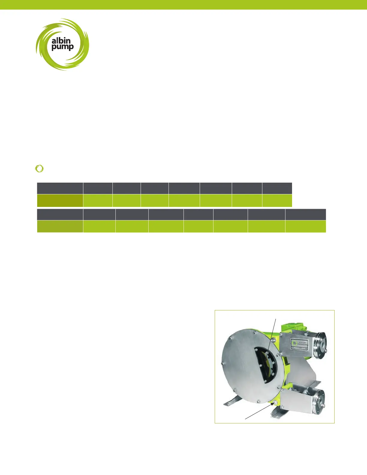
6.1 - EMPTYING AND FILLING OF THE LUBRICANT
Refer to §6.6 to know the periodicity of lubricant change.
1 - Stop the pump.
2 - Place a tray underneath the drain plug (REF 23).
REF 15 and 46
REF 23
4.5 - LIFTING THE PUMP
Pumps are provided with two lift holes (eyebolts) placed on the upper part of the frame. While lifting the pump, respect the
following points:
- Lift the complete hose pump using the lifting rings plus additional support on the gearbox and the motor using suitably
rated straps or slings.
- Never exceed the upper limits of lift and control the motorized pump weights in the table below.
- The motorized pump, given its centre of gravity, will tend to overbalance on the pump head side. Make sure that the
persons are at a secure distance from the pump to avoid any risk of wound.
- Never raise the pump otherwise than by the pump’s lifting rings.
- Never raise the pump by its orices nor by its brackets.
PUMP ALH05-10 ALH15 ALH20 ALH25 ALH32 ALH40 ALHX40
Approx. Weight
25 (55.1) 35 (77.2) 35 (77.2) 80 (176.4) 130 (286.6) 145 (319.7) 210 (463)
PUMP
ALH50 ALH65 ALHX65 ALHX80 ALH80 ALH100 ALH125
Approx. Weight
315 (694.5) 335 (738.5) 500 (1102.3) 700 (1543) 930 (2050.3) 1250 (2755.8) 1750 (3858.1)
WEIGHT
kg (lbs)