12 albinpump@irco.com Albinpump.com Albin Pump ALH Instruction Manual
since 1928
ALH
Maintenance
3 - If necessary, install a tap and a drain circuit instead of the drain plug (REF 23).
4 - Make sure that this tray can contain the quantity of lubricant during the drainage process, see lubricant volume
table §9.7.
5 - Unscrew the plug (REF 23) and undertake emptying.
6 - Position and tighten the plug (REF 23) by applying PTFE band or waterproof paste or close the drain tap
.
NOTE : If the pump is mounted with the inlet/outlet positioned upwards, lubricant drainage is obtained by unscrewing cover
screws in the lower part.
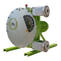
7 - Remove the sight glass (REF 15) as well as its seal (REF 46) and ll the casing with the ALBIN lubricant, see lubricant
table §9.7. You can also ll the casing by the breather cap (REF 52) situated at the back of the pump casing. The
required lubricant level is underneath the bottom edge of the sight glass (see photo beneath).
8 - Check the state of the seal (REF 46) and reassemble the sight glass (REF 15) or tighten the breather cap (REF 52).
MAX LEVEL
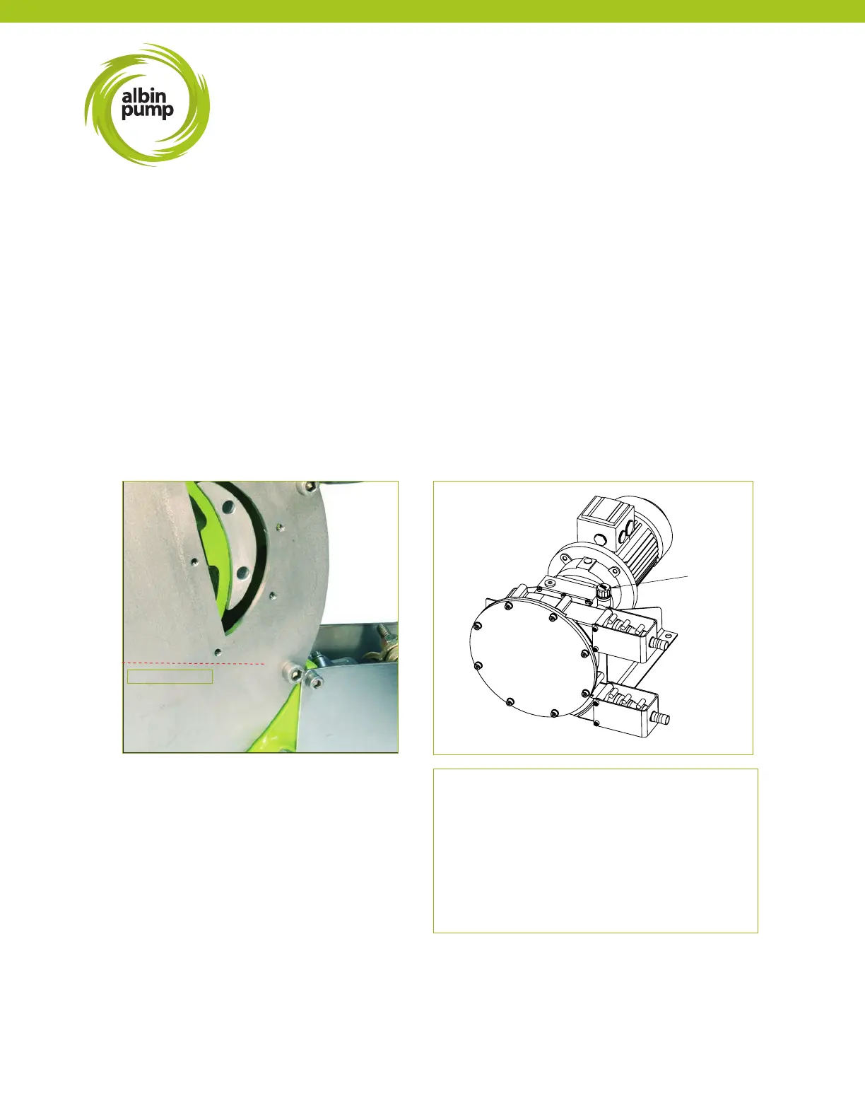
FOR MODELS ALH05, ALH10, ALH15
and ALH20:
Unscrew higher breather plug (REF 52) of the
pump. Place a funnel inside the plug hole and ll
the casing with the ALBIN lubricant
(see lubricant table §9.7). The necessary volume
of lubricant is just underneath the shaft line.