20 albinpump@irco.com Albinpump.com Albin Pump ALH Instruction Manual
since 1928
PUMPS FROM ALHX80 TO ALH125
(refer to the nomenclature for the landmarks of parts §9.3
1 - Undertake the same operation steps 1 to 10 as for pumps ALH05 to ALH65.
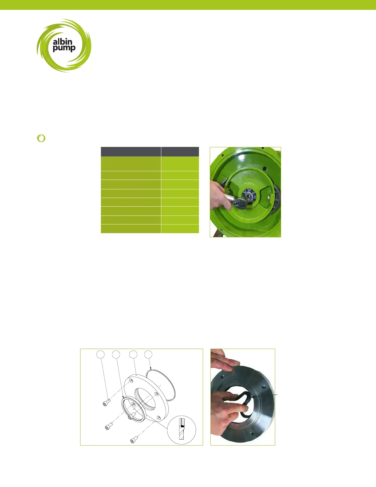
2 - Disassemble the seal ange (REF 25) and withdraw the damaged shaft seal with a screwdriver or a similar tool.
3 - Take the new shaft seal (REF 26) between the thumb and the index and by tightening your ngers, form an “8“ gure.
The seal can now be inserted into its groove by respecting the mounting position (see drawing).
4 - Mount the gear motor on the pump casing (see operation step 13).
5 - Replace the O-ring (REF 67) if necessary and reassemble the seal ange.
6 - For pumps ALHX80 and ALH80, undertake operation steps 14 to 17 of previous chapter. For pumps ALH100 and
ALH125, undertake operation step14 of previous chapter. Then block the wheel with the washer (REF 60) and the screw
(REF 59) and nish with operation steps 16 and 17 of previous section.
67252643
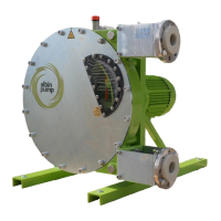
15 - Cross tighten the expansible hub with a dynamometric spanner, certied tooling required, to the correct torque gure
check the wheel position once again and re-adjust if necessary. Refer to §9.10 for expansible hub assembly and
disassembly.
16 - Mount the cover seal (REF 10) in its groove and mount the cover.
17 - Mount the pump hose as stated in §6.3.3.
PUMP TYPE TORQUE
ALH05, ALH10, ALH15,
ALH20
15 (11.1)
ALH25, ALH32, ALH40 13 (9.6)
ALHX40 34 (25.1)
ALH50, ALH65 35 (25.8)
ALHX65 90 (66.3)
ALHX80 110 (81.1)
ALH80 (sha Ø90) 110 (81.1)
ALH80 (sha Ø100) 190 (140.1)
ALH
Maintenance
TORQUE
Nm (Ft-lbs)
REF 26