Chapter 3 Components and Power Supply
The following chapter provides information on the OA5725R router family chassis and its components. This informa-
tion includes:
• Components.
• Assembly instructions.
• Power supply.
• RST button.
• Data connection.
• Inserting the SIM card.
3.1 Components
3.1.1 Front Panel
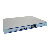
The following figure shows the front panel.
Fig. 2: Front panel
The front panel elements are as follows:
Elements table for the front panel
Item Description
A RF2. WWAN antenna connector.
B RST. Reset button. For further information on how the reset button works, please
see section RST Button on page 11 further on in this chapter.
C 6-port Fast Ethernet Switch
D DSL. RJ-11 connector permitting connection to an ADSL/ADSL2+/VDSL over
ISDN network.
E CONF. DB9 connector providing Access to the device local console for configura-
tion and monitoring purposes. (This connector can also be used as an RS-232
asynchronous DCE serial port).
F I/O. ON/OFF power switch, position I for ON and position O to switch it OFF.
G RF1. WWAN antenna connector.
H POWER. Power connection. For more information on the power connection,
please see section Connecting the Power Supply on page 10.
Alcatel-Lucent Enterprise
3 Components and Power Supply
OA5725R Router 5