Red
Off
-100dBm.
Coverage level below -100dBm.
Cellular interface is not active.
100 Associated to each Ethernet switch
connector (LAN1…LAN6)
Amber ON -> Connection at 100Mbps
OFF -> Connection at 10Mbps
LNK Associated to each Ethernet switch
connector (LAN1…LAN6)
Green ON -> Ethernet connection (link) es-
tablished:
- Steady: Data is not being trans-
ferred.
- Flashing: Data is being transferred.
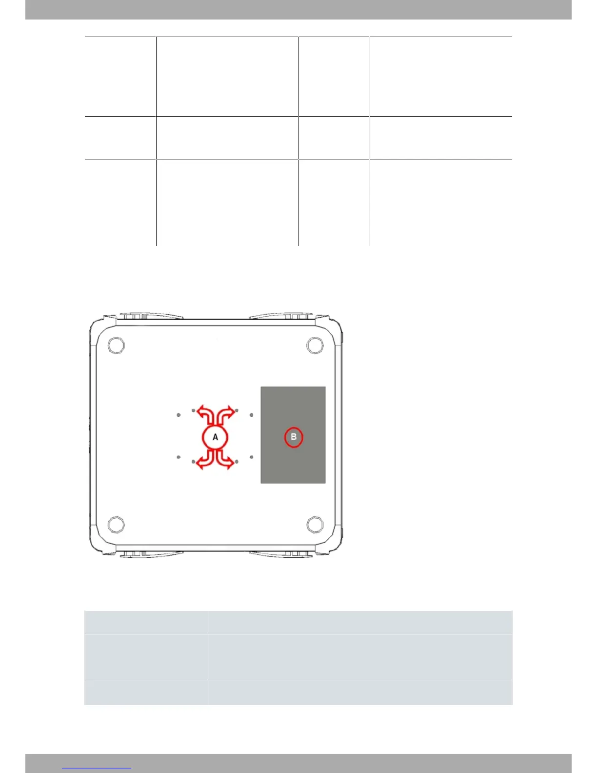
3.1.2 Underside Panel
The following figure shows the underside panel:
Fig. 4: Underside panel
The underside panel elements are as follows:
Underside panel elements table
Item Description
A Slots for the accessories to attach the device to the DIN rail mount. For further in-
formation on this accessory, please see section Installing a DIN rail mount ac-
cessory on page 8
B Label with product information
Alcatel-Lucent Enterprise
3 Components and Power Supply
OA5725R Router 7