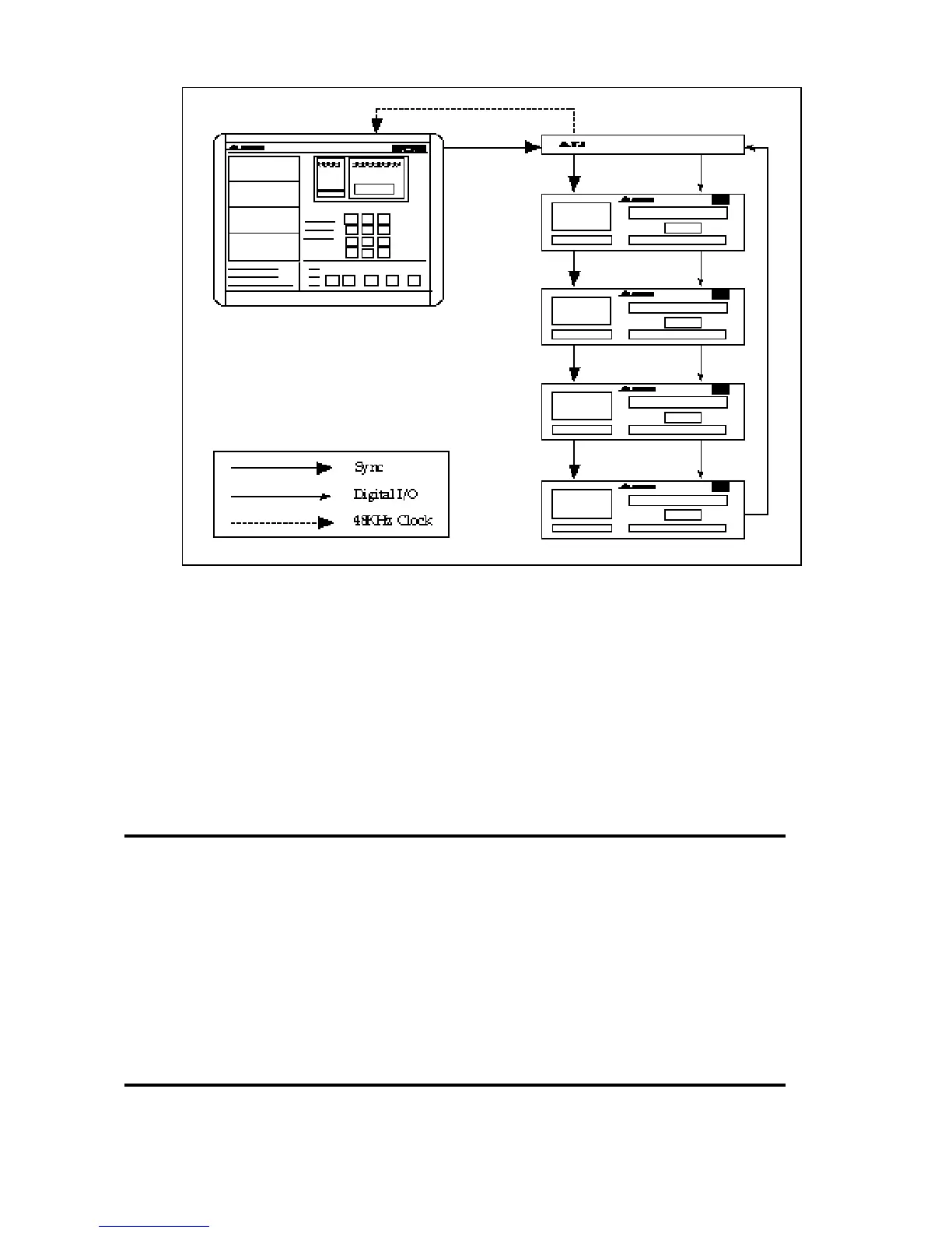
5. When recording audio from AES/EBU or S/PDIF source, the
ADAT(s) must be synchronized to the incoming digital signal.
This means you will not only need to connect the AI-1 to the
digital bus (as described above), but you must also connect the AI-
1’s 48 KHz output to the BRC’s 48 KHz input, using a standard
shielded BNC cable.
For more information about sample rate conversion and interfacing
the AI-1 with other digital audio equipment, please refer to the AI-1’s
owners manual.
2.3 SMPTE IN/OUT
The SMPTE input and output connectors are 1/4" jacks. SMPTE
input is for syncing to an external device. SMPTE output is for
generating sync to an external device.
For more information about SMPTE, see section 5.0.
2.4 MIDI IN/OUT