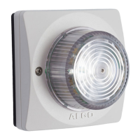
8138 SIP Multicolor Strobe Light
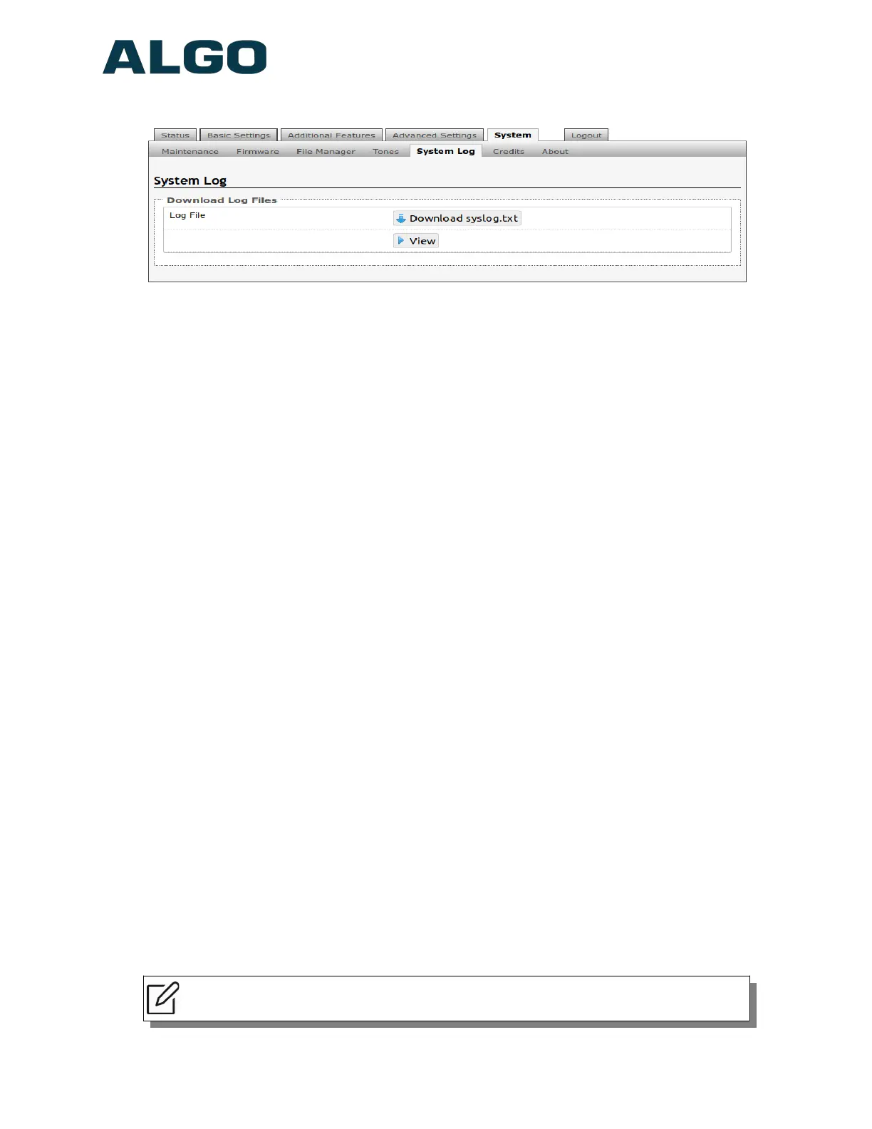
System Tab – System Log
System log files are automatically created and assist with troubleshooting in the event the
8138 SIP Strobe Light does not behave as expected.
Wiring Connections
Network Connection
The strobe provides a RJ45 jack for network connection. A cable run from the switch can
be terminated to a modular jack with connection by patch cord, or terminated with a RJ45
plug.
PoE (Power over Ethernet) must be 48V 350 mA IEEE 802.3at PoE+ or 802.3af compliant
whether provided by the network switch or injector.
There are two lights on the Ethernet jack:
Green light: On when Ethernet is working, flickers off to indicate activity on the port.
Amber light: Off when successful 100Mbps link is established. Typically On only
briefly at power up.
Under normal conditions, the Amber light will turn on immediately after the Ethernet cable
is first connected. This indicates that PoE power has been successfully applied. Once the
device connects to the network, it will switch to the Green light instead, which will typically
flicker indicating traffic on the network.
Connecting Input Devices
The dry contact relay on the 8138 SIP Strobe Light can be prompted by any normally
open, normally closed switch, Algo 1202 Call Button and Algo 1203 Call Switch. The input
switches can be connected to the back of the back of the 8138 via the “IN”.
Connection options can be configured from normally open switch, to normally closed
switch, to Algo 1202 Call Button with large blue button, to Algo 1203 single gang backlit
Call Switch, or as an EOL resistor termination. The connection options can then be
configured to complete an ‘Action’ when Relay Input is triggered.
Note: See “Additional Features Tab – Input/Output” section of this user doc for
additional information on input device configuration
Document 90-00102C
11/27/2019
Page 49
Algo Communication Products Ltd
4500 Beedie St Burnaby BC Canada V5J 5L2
www.algosolutions.com
(604) 454-3792
support@algosolutions.com