17ALI-NS8014VR IP PTZ Camera Installation and Setup Guide
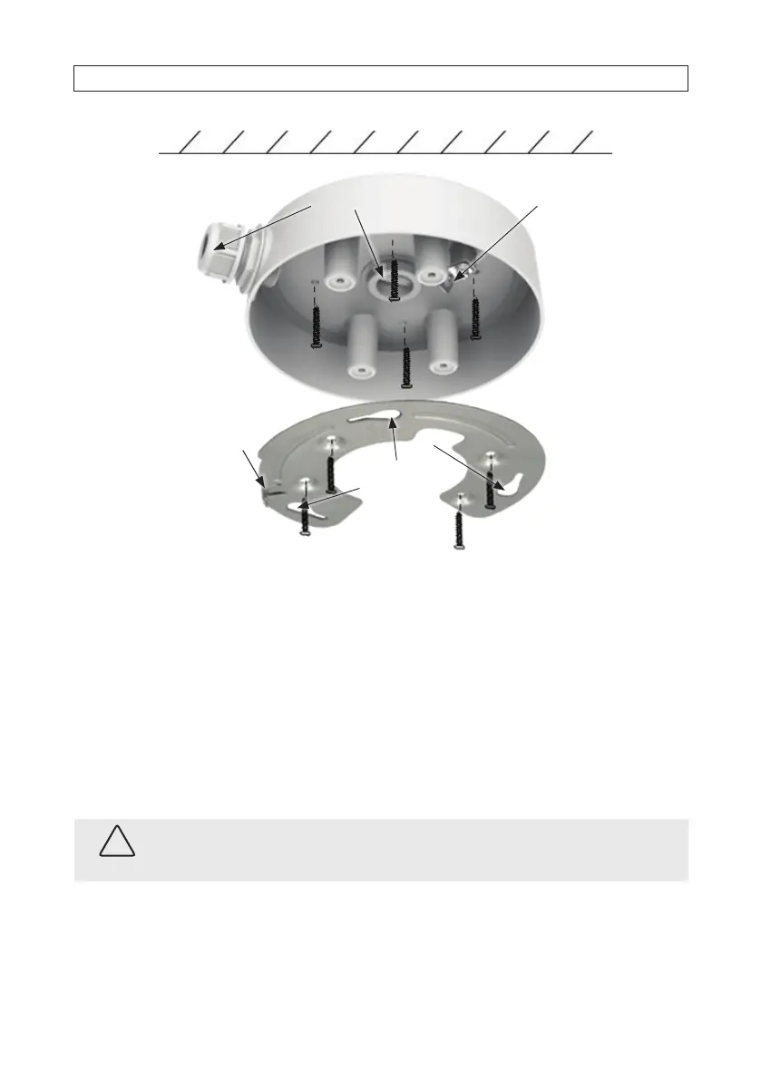
Slots (3) on
adapter plate
Tab for lock
screw
ALI-AJ10
Junction Box
Adapter plate
Ceiling
Hook for
safety cable
Extension cable access
5. Attache the adapter plate to the junction box using the screws provided. Align the screw holes in the plate with the posts in
the junction box.
6. Route LAN, power, and accessory extension cables to the installation location. These cables can be routed into the junction box
through the base or through the adapter on the side. See “2.6 Connecting drop cables” on page 18 for more information
about extension cables.
7. Attach the safety cable provided to the camera base. A hole in the base is provided for the safety cable screw. Attach the other
end of the cable to the hook in the junction box. The camera should hang securely on the junction box.
8. Connect the LAN, power and accessory extension cables to camera drop cable, as needed. Protect all connections from
contamination.
CAUTION
Failure of this product due to contamination of drop cable connections is considered an installation error, and voids the
warranty of the product.
9. While storing extra cable in the junction box above the adapter plate, position the camera on the adapter plate such that
the three raised screw heads (see below) in the camera base t into the three slots in the plate, and then rotate the camera
clockwise to fully seat the screw heads in the slots.
SECTION 2: INSTALLATION