ARTIX-7 FPGA Development Board AX7101 User Manual
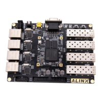
Figure 3-5-2: USB to serial port on the Carrier Board
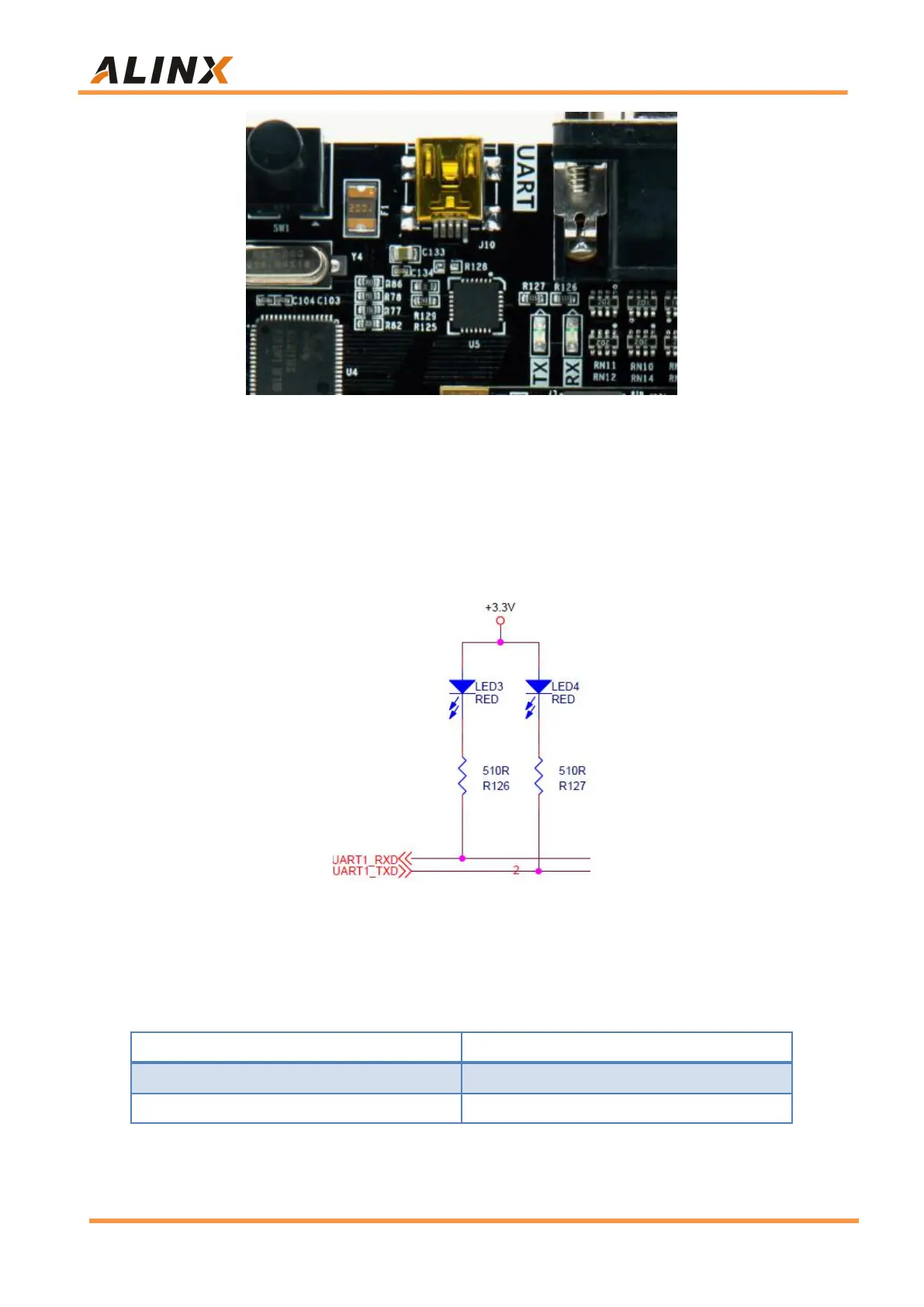
Two LED indicators (LED4 and LED3) are set for the serial port signal, and
the silkscreen on the PCB is TX and RX, indicating that the serial port has data
transmission or reception, as shown in the following Figure 3-5-3
Figure 3-5-3: Serial Port communication LED Indicators Schematic
USB to serial port pin assignment: