ARTIX-7 FPGA Development Board AX7101 User Manual
The 2
nd
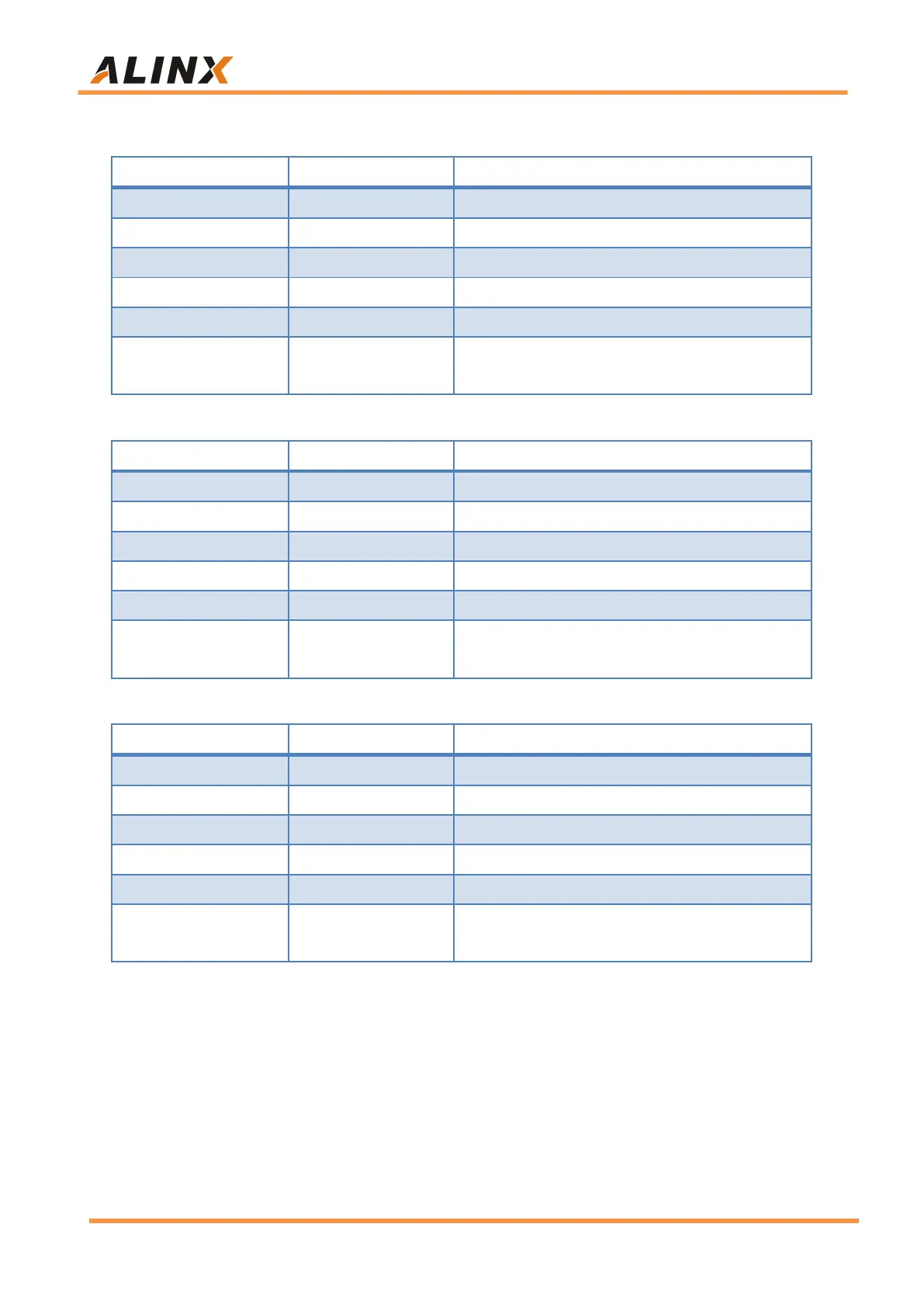
fiber interface FPGA pin assignment is as follows:
SFP2 Data Transfer (Positive)
SFP2 Data Transfer (Negative)
SFP2 Data Receiver (Positive)
SFP2 Data Receiver (Negative)
SFP2 Optical Transfer Disable, active high
SFP2 Optical LOSS, High level means no light
signal is received
The 3
rd
fiber interface FPGA pin assignment is as follows:
SFP3 Data Transfer (Positive)
SFP3 Data Transfer (Negative)
SFP3 Data Receiver (Positive)
SFP3 Data Receiver (Negative)
SFP3 Optical Transfer Disable, active high
SFP3 Optical LOSS, High level means no light
signal is received
The 4
th
fiber interface FPGA pin assignment is as follows:
SFP4 Data Transfer (Positive)
SFP4 Data Transfer (Negative)
SFP4 Data Receiver (Positive)
SFP4 Data Receiver (Negative)
SFP4 Optical Transfer Disable, active high
SFP4 Optical LOSS, High level means no light
signal is received
Part 3.4: VGA display interface
The VGA interface is the most important interface on a computer monitor,
also known as the D-Sub interface. The VGA interface is a D-type interface with
a total of 15 pinholes, divided into three rows, five in each row. More important
are three RGB color component signals and two scan sync signals HSYNC and