EasyManua.ls Logo

Alinx ARTIX-7 - Part 3.7: JTAG Interface

Alinx ARTIX-7
51 pages
Print Icon
To Next Page IconTo Next Page
To Previous Page IconTo Previous Page
Loading...
ARTIX-7 FPGA Development Board AX7101 User Manual
47 / 51
www.alinx.com
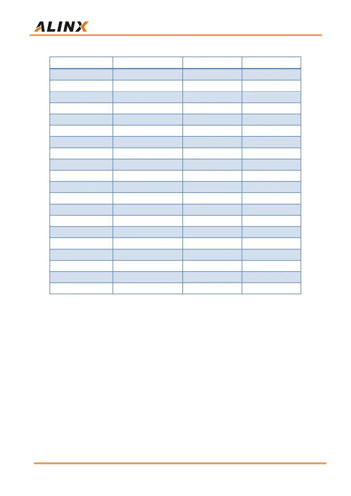
J11 Expansion Header Pin Assignment
J11 Pin Number
FPGA Pin
J11 Pin Number
FPGA Pin
1
GND
2
+5V
3
B22
4
C22
5
A20
6
B20
7
F20
8
F19
9
J16
10
F15
11
F21
12
M17
13
A21
14
B21
15
D21
16
E21
17
G18
18
G17
19
H19
20
J19
21
G16
22
G15
23
D19
24
E19
25
C20
26
D20
27
A19
28
A18
29
E18
30
F18
31
C19
32
C18
33
B18
34
B17
35
C17
36
D17
37
GND
38
GND
39
+3.3V
40
+3.3V
Part 3.7: JTAG Interface
A JTAG interface is reserved on the AX7101 FPGA carrier board for
downloading FPGA programs or firmware to FLASH. In order to prevent
damage to the FPGA chip caused by hot plugging, a protection diode is added
to the JTAG signal to ensure that the voltage of the signal is within the range
accepted by the FPGA to avoid damage of the FPGA chip.