ARTIX-7 FPGA Development Board AX7101 User Manual
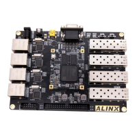
Figure 3-9-1: The User LEDs Schematic
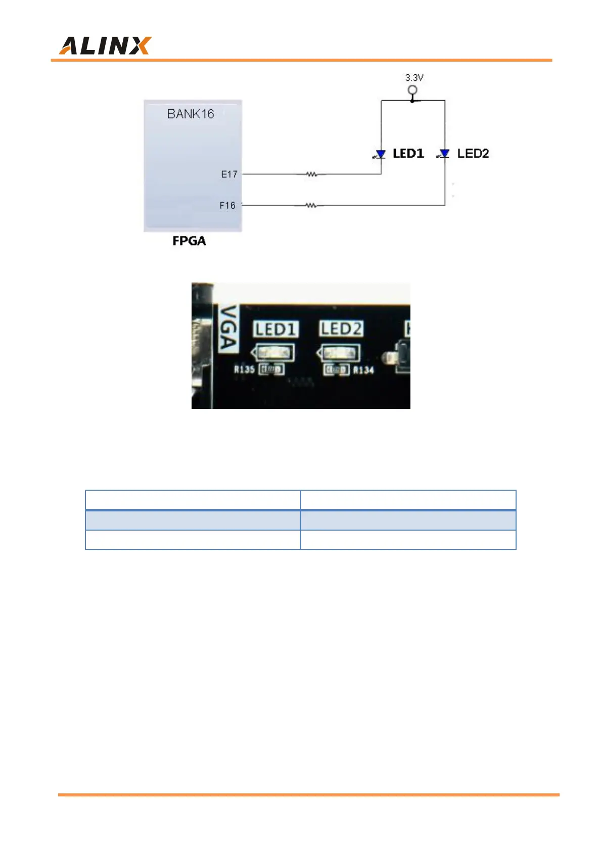
Figure 3-9-2: The User LEDs on the Carrier Board
Pin assignment of user LED lights
Part 3.10: Power Supply
The power input voltage of the The AX7101 FPGA carrier board is DC12V.
The Carrier Board is converted into +5V and +3.3V two-way power supply
through two DC/DC power chip MP1482. In addition, the +5V power supply on
the Carrier Board supplies power to the core board through the inter-board
connector. The power supply design on the expansion is shown in Figure
3-10-1.