ARTIX-7 FPGA Development Board AX7101 User Manual
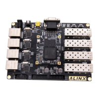
Figure 3-7-1: JTAG Interface Schematic
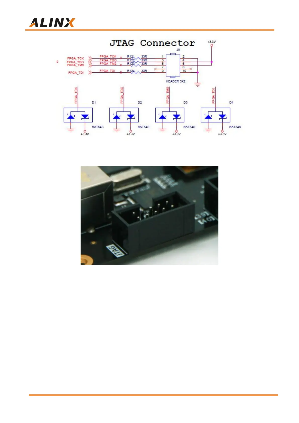
Figure 3-7-2: JTAG Interface on the Carrier Board
Be careful not to hot swap when JTAG cable is plugged and unplugged.
Part 3.8: Keys
The AX7101 FPGA carrier board contains two user Keys KEY1~KEY2. All
Keys are connected to the normal IO of the FPGA. The Key is active low. When
the Key is pressed, the IO input voltage of the FPGA is low. When no Key is
pressed, The IO input voltage of the FPGA is high. The circuit of the Key part is
shown in Figure 3-8-1.