ARTIX-7 FPGA Development Board AX7101 User Manual
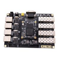
Figure 3-8-1: Key Schematic
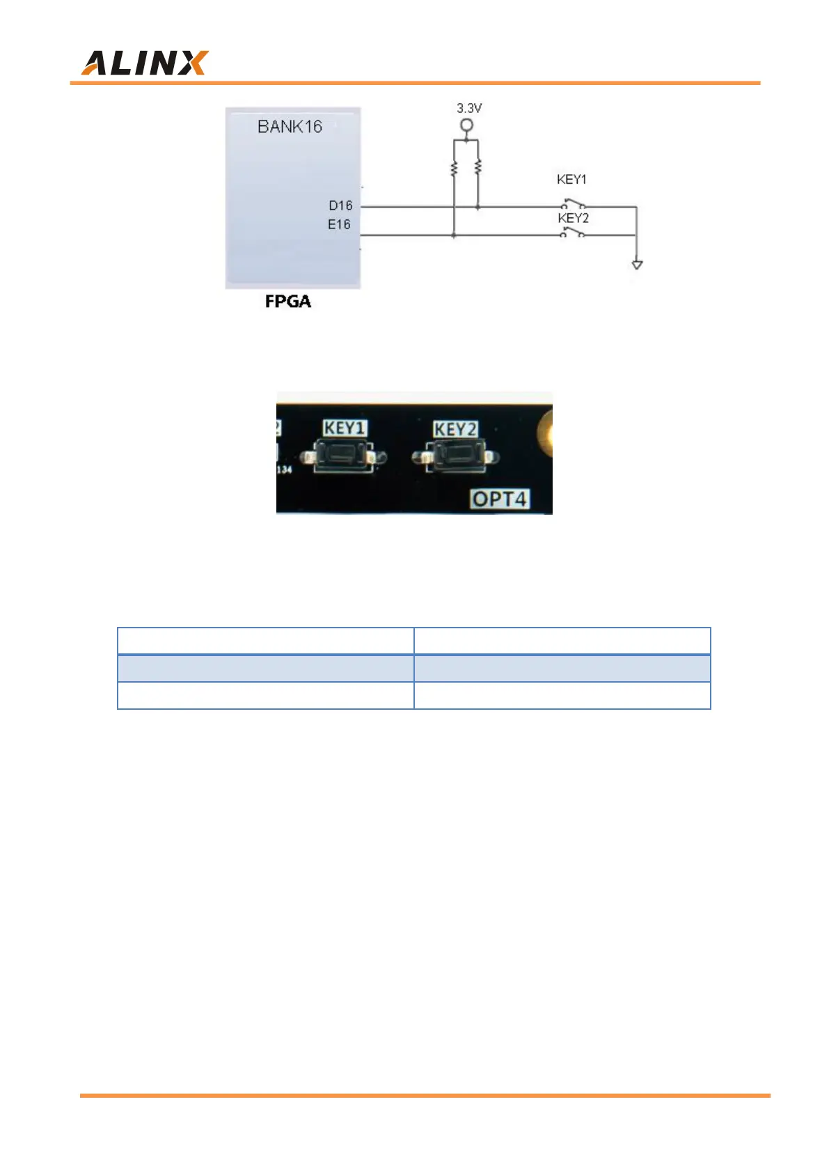
Figure 3-8-2: Four Keys on the carrier board
Keys Pin Assignment
Part 3.9: LED Light
There are three red LEDs on the AX7101 FPGA Carrier Board, one of
which is the power indicator (PWR), two are users LED lights (LED1~LED2).
When the board is powered on, the power indicator will light up; User
LED1~LED2 are connected to the normal IO of the FPGA. When the IO voltage
connected to the user LED is configured low level, the user LED lights up.
When the connected IO voltage is configured as high level, the user LED will
be extinguished. The schematic diagram of the user LEDs hardware
connection is shown in Figure 3-9-1.